

LED street lamp
A technology of LED street lamps and lamp holders, which can be used in cooling/heating devices of lighting devices, outdoor lighting, sustainable buildings, etc., and can solve problems such as poor heat dissipation performance
- Summary
- Abstract
- Description
- Claims
- Application Information
AI Technical Summary
Problems solved by technology
Method used
Image

Examples
Embodiment 1
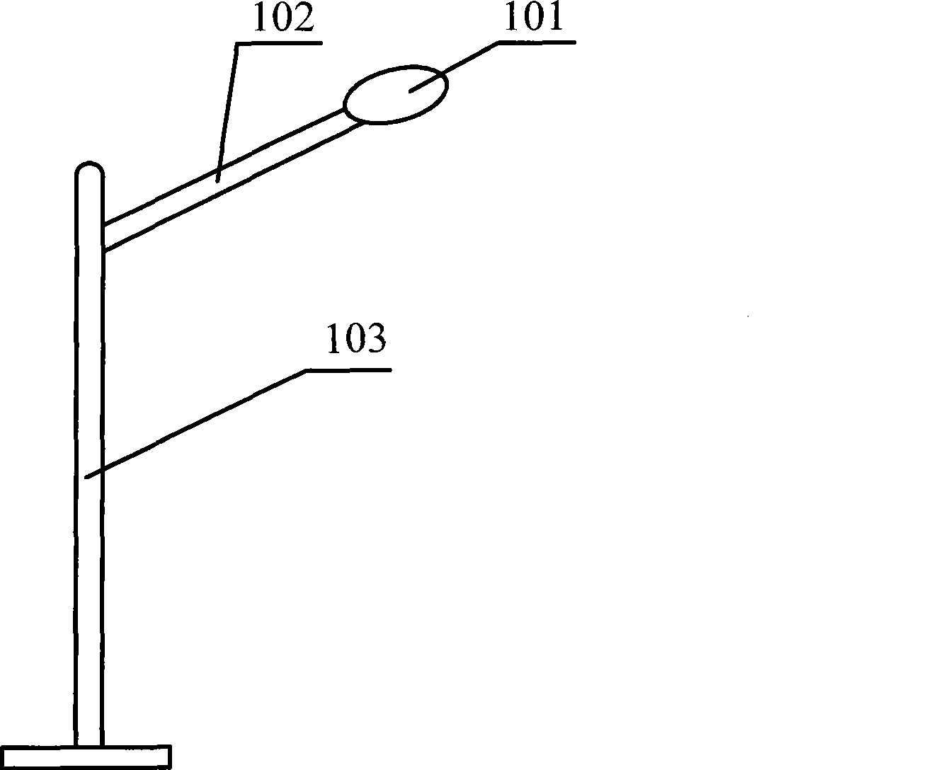
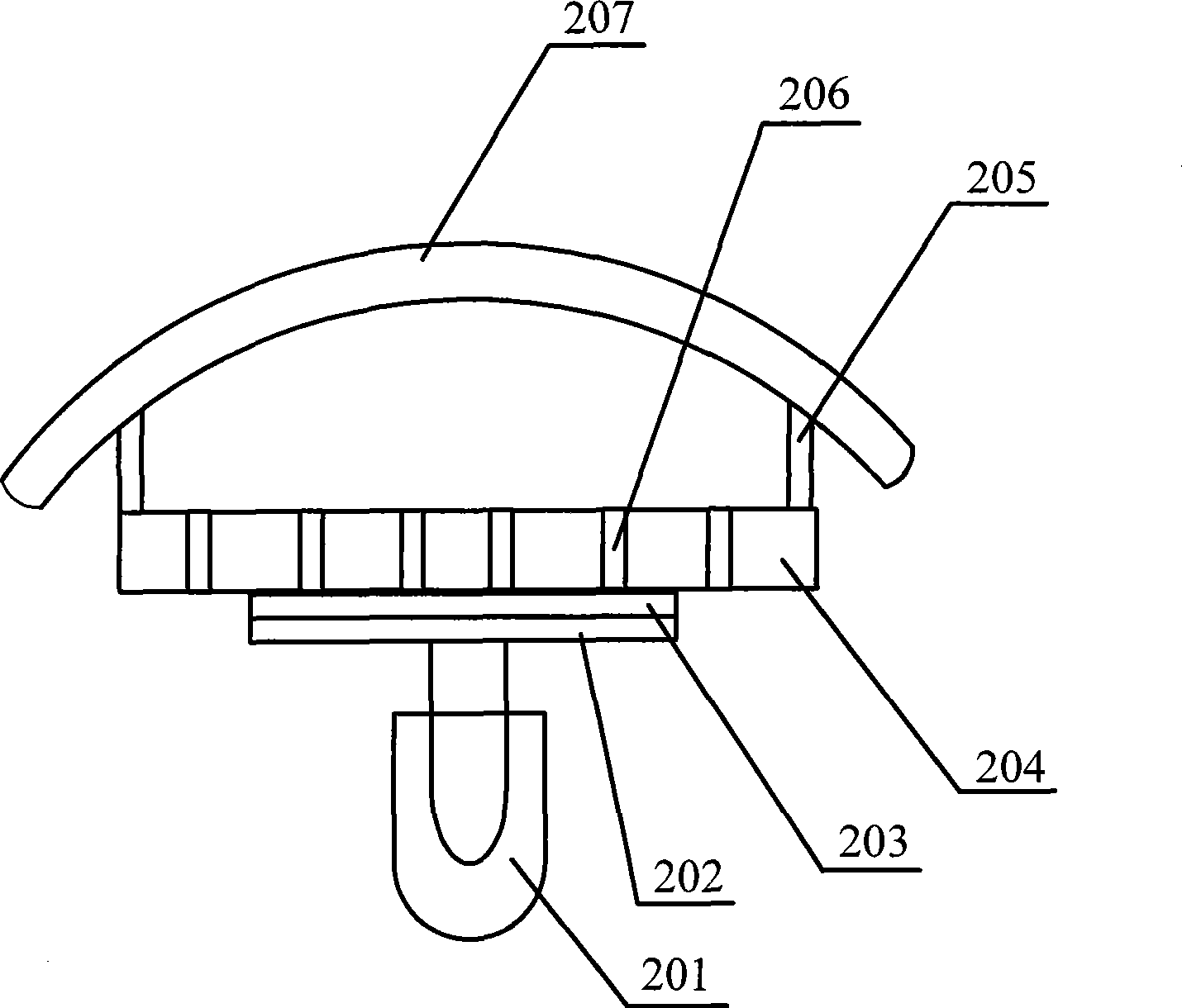
[0030] Such as figure 1 As shown, the LED street lamp of this embodiment includes a lamp post and a lamp body 101, and the lamp body is as figure 2 As shown, the light pole includes a main pole 103 and a pole 102, the main pole 103 is used to support the entire LED street lamp, so that the LED street lamp can be fixed on a specific place, and the pole 102 is used to make the lamp body 101 Protrude above the road surface for road lighting.
[0031] Such as figure 2 As shown, the lamp body 101 includes a lamp holder 204 and a PCB board 202; wherein the lamp holder 204 can be set as a plane plate, can also be set as a curved plate, can also be a wave-shaped plate or other customized shapes, and the inside of the lamp holder A concentrating cup can be provided to gather the light and irradiate the light from a certain direction. In addition, a film layer can be directly coated on the side of the lamp holder facing the LED light-emitting diode, and the film layer can be a The ...
Embodiment 2
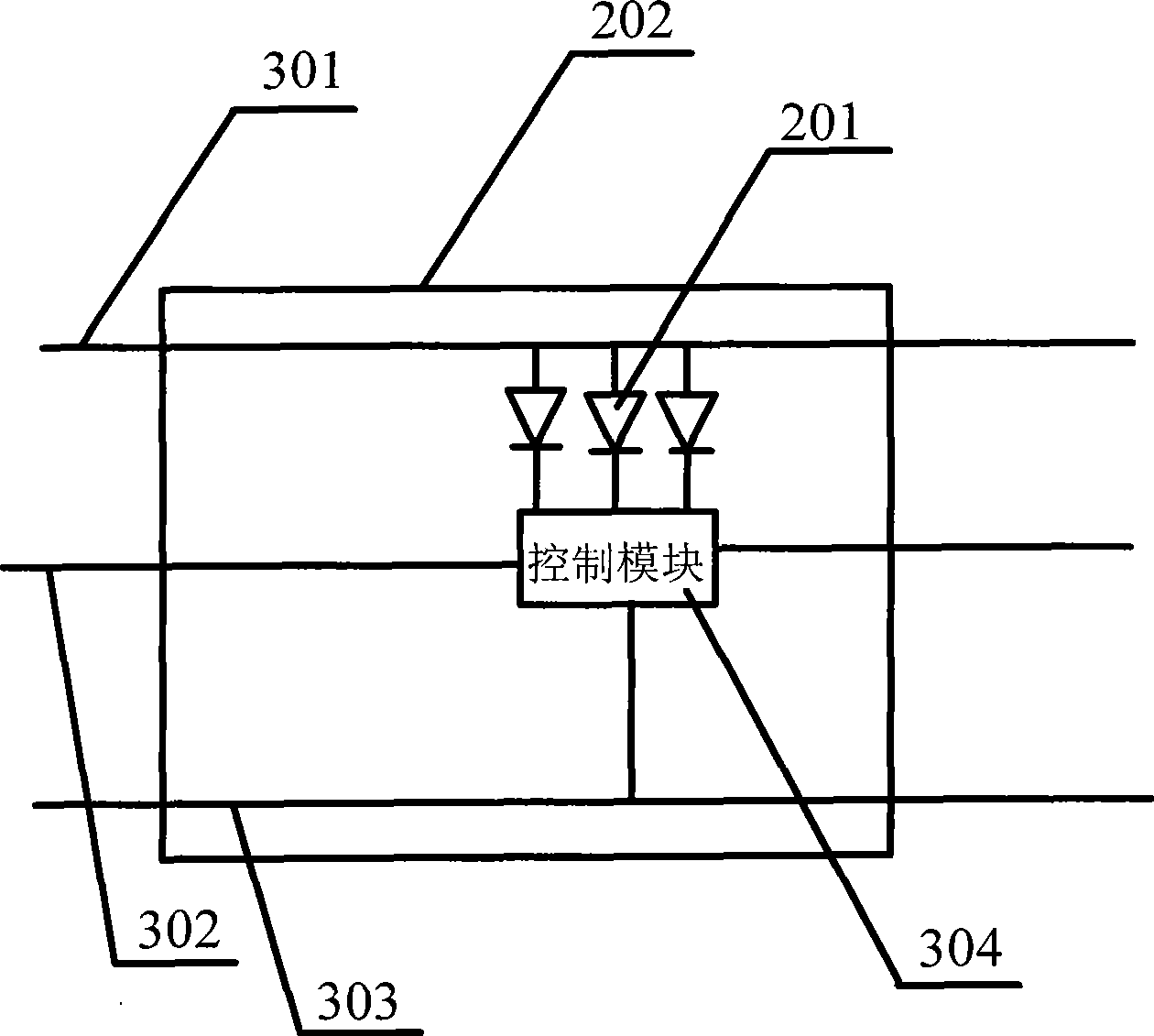
[0048] On the basis of each example in Embodiment 1, a plurality of positive power lines 301 and a plurality of negative power lines 303 may also be arranged on the PCB 202 .
[0049] Each power supply line can be set to include multiple positive power supply lines and multiple negative power supply lines. Each positive power supply line and each negative power supply line are respectively connected to an external power supply to provide voltage for the LED light-emitting diode 201, so as to ensure that the interior of the LED street lamp The normal operation of each LED light-emitting diode and other electronic components; other electronic components may be the control module 304, or resistors installed to prevent excessive current.
[0050] Multiple pairs of positive and negative power lines can be connected to LED light-emitting diodes and other electronic components respectively. When a certain pair of positive and negative power lines is disconnected, it will not affect th...
Embodiment 3
[0054] Such as Figure 4 As shown, on the basis of the above examples, at least one group of LED light-emitting diodes is arranged on the PCB board 202, and each group of LED light-emitting diodes includes at least one red LED light-emitting diode, at least one green LED light-emitting diode and at least one blue LED light-emitting diode. diode. The LED light-emitting diodes including three colors can be controlled by the control module to emit light of any color in nature, for example, white light or yellow light of common colors.
[0055] More than two groups of LED light-emitting diodes can be arranged as required. For example, six groups of LED light-emitting diodes are arranged in the LED street lamp of this embodiment, and each group of LED light-emitting diodes includes at least one red LED light-emitting diode, at least one green LED light-emitting diode and at least one green LED light-emitting diode. 1 blue LED light emitting diode. One group of LED light-emitting ...
PUM
 Abstract
Description
Claims
Application Information