Ultrasonic cavitation pressure measuring device and measurement method thereof

A measuring device, ultrasonic technology, applied in the direction of fluid pressure measurement using acoustic methods, etc., to achieve the effect of ensuring accuracy, small size, and high natural frequency

Inactive Publication Date: 2009-04-29
TAIYUAN UNIV OF TECH
View PDF0 Cites 11 Cited by
  • Summary
  • Abstract
  • Description
  • Claims
  • Application Information

AI Technical Summary

Problems solved by technology

[0004] The purpose of the present invention is to provide a measuring device and method for ultrasonic cavitation pressure, so as to solve the problem of quantitatively measuring ultrasonic instantaneous cavitation pressure

Method used


Image

  • Ultrasonic cavitation pressure measuring device and measurement method thereof
  • Ultrasonic cavitation pressure measuring device and measurement method thereof
  • Ultrasonic cavitation pressure measuring device and measurement method thereof

Examples


Embodiment 1

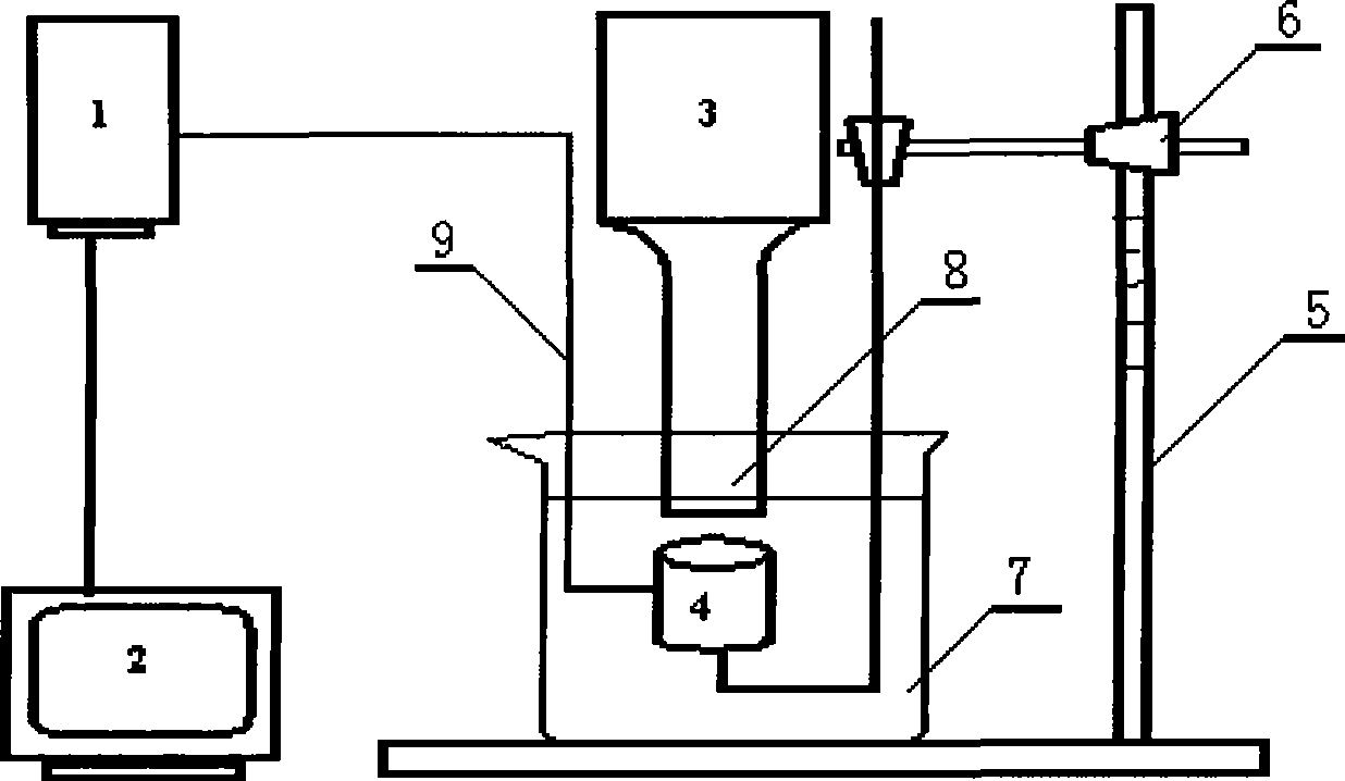
[0023] The invention relates to a measuring device for ultrasonic cavitation pressure, which includes an ultrasonic generator, a piezoelectric quartz force sensor, a charge amplifier, a computer data acquisition device, and a support that can adjust the precise height. The device is to set the piezoelectric quartz force sensor on the support so that the measuring surface is facing the probe of the ultrasonic generator, and then the signal line of the sensor is connected to the input end of the amplifier, and the output end of the amplifier is connected to the computer data acquisition device.

[0024] The main principle of the present invention is to measure the pressure of ultrasonic wave in water with piezoelectric quartz force sensor. Piezoelectric sensor is a kind of electromechanical transducer, which is characterized by simple structure, firmness, convenient installation, small size, light weight and long life; wide frequency response range and good stability. Using the ...

Embodiment 2

[0026] The present invention is used for the measuring method of measuring device, and concrete steps are as follows:

[0027] (1) Measurement steps

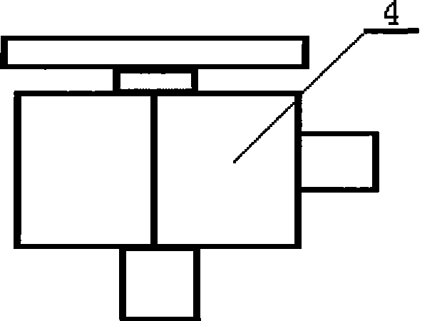
[0028] 1. The structure of the sensor see figure 2 , Before measuring, the signal socket of the sensor should be connected with the signal line, and the signal line connection should be sealed with epoxy resin to achieve absolute waterproof effect, and it should be used after 24 hours of drying.

[0029] 2. Fix the sensor on a metal bracket that can move up and down. The moving distance can be measured by the scale on the bracket, such as figure 1 shown.

[0030] 3. Put the sensor into the water, the measuring surface of the sensor is facing the lower part of the ultrasonic probe, and adjust the distance between the measuring surface and the probe.

[0031] 4. Immerse the ultrasonic probe 5mm below the horizontal surface, connect the signal line of the sensor to the input terminal of the charge amplifier, and connect the out...


PUM


Abstract

The invention discloses a device and a method for measuring the supersonic cavitation pressure. The device is as follows: a sensor is arranged on a support; a measuring surface faces to a supersonic generator probe; and a signal line is connected with the input end of an amplifier the output end of which is connected with a data acquisition device. The method is to arrange the sensor in water to adjust the distance of the probe and the sensitivity of a charge amplifier, to select a gain measuring range, acquires electrical signals outputted by the charge amplifier, to start a supersonic generator to measure, record and store voltage data, to convert an obtained data curve of voltage and time so as to obtain the supersonic cavitation pressure value. The method performs quick, instant, dynamic, multi-point, long-term and real-time monitoring and acquisition on the data, breaks through the limitation of the prior monitoring method, and can measure the instantaneous value or the mean value. The device has large rigidity as for a structure, is simple, convenient, reliable and accurate, and has high natural frequency. The device and the method are suitable for variation research of physical properties and the chemical properties of liquid which is subjected to phonochemical reaction, equipment cavitation erosion and so on.

Description

technical field [0001] The invention relates to a device and method for measuring the cavitation pressure of microbubbles in a liquid, in particular to a device and a method for measuring the cavitation pressure of microbubbles in a dynamic liquid under the action of ultrasonic waves. Background technique [0002] Ultrasonic cavitation refers to the dynamic process of growth and collapse of micro-air nuclei cavitation bubbles existing in liquids that vibrate under the action of sound waves, and when the sound pressure reaches a certain value. Cavitation generally includes three stages: formation, growth and violent collapse of cavitation bubbles. After the ultrasonic wave is passed through the liquid, tens of thousands of tiny bubbles are generated due to the vibration of the liquid, that is, cavitation bubbles. These bubbles grow in the negative pressure zone formed by the longitudinal propagation of ultrasonic waves, and quickly close in the positive pressure zone, thereb...

Claims


Application Information

Patent Timeline
Patent Type & Authority Applications(China)
IPC IPC(8): G01L11/06
Inventor 王保成张瑞珍
Owner TAIYUAN UNIV OF TECH
Why Eureka
Try Eureka