Ultrasonic motor driving method
A technology of ultrasonic motor and driving method, which is applied in the direction of generator/motor, electrical component, piezoelectric effect/electrostrictive or magnetostrictive motor, etc., which can solve the problem of increasing difficulty and boosting ratio of DC/DC switching circuit Increase and other problems, to achieve the effect of improving efficiency, automatic balance of input current, and simple circuit
- Summary
- Abstract
- Description
- Claims
- Application Information
AI Technical Summary
Problems solved by technology
Method used
Image
Examples
Embodiment 1
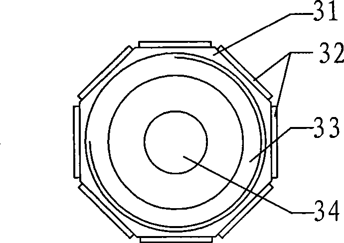
[0095] According to FIG. 3 , the ultrasonic motor of this embodiment includes a stator 31 and a rotor 33 with a central circular hole. The stator 31 is composed of a hollow cylindrical metal body on which several piezoelectric elements 32 are fixed, and the rotor 33 is composed of a revolving housing 33 embedded with an optical lens group 34 . The base body of the stator 31 and the rotor 33 are matched by threads 35, that is, the inner wall of the central circular hole of the stator 31 is provided with internal threads, and the outer surface of the rotor 33 is provided with corresponding external threads, both of which have the same pitch and nominal diameter. The shape of the stator base 31 is polyhedral or cylindrical and has a hollow inner wall. Its metal material makes the piezoelectric elements on it have a common node. The surface of the thread is wear-resistant or coated with wear-resistant materials. The cross-section of the thread can be It is a variety of forms such ...
Embodiment 2
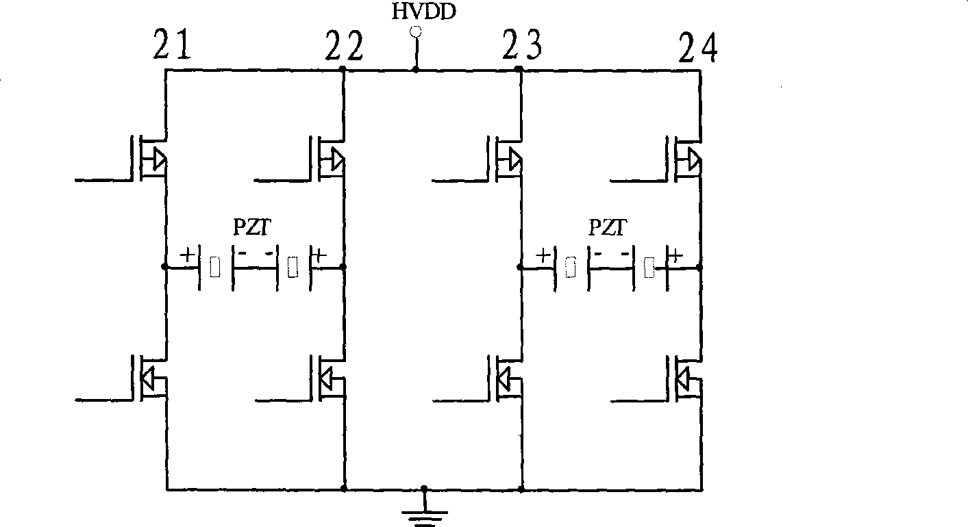
[0099] Embodiment 2 differs from Embodiment 1 only in the circuit for driving the power supply. Such as Figure 7 shown in Figure 5b A step-up DC / DC switch circuit is added before the bridge inverter circuit shown in order to increase the supply voltage. For example, in the case of battery-powered applications, use a step-up DC / DC switching circuit to increase the voltage to a certain value.
[0100]Of course, if the power supply voltage is higher than the driving voltage required by the piezoelectric element, it can also be realized by step-down DC / DC in the same way.
Embodiment 3
[0102] The ultrasonic motor of embodiment 3 is shown in Fig. 8, and its basic structure is similar to that of Fig. 3, the only difference is that the number of piezoelectric elements is different, which is 6, so that the motor can be driven by a three-phase power supply in the following manner:
[0103] The polarization of the piezoelectric element and the wiring of its driving power are as follows: Figure 9 shown. Piezoelectric sheets 92-94, 96-98 are all positively polarized, and connected in sequence Figure 5b After the midpoint of the first bridge arm 51, the second bridge arm 52, and the third bridge arm 53 of the circuit shown, the piezoelectric sheet is excited by the three-phase power supply and forms a clockwise rotating vibration traveling wave on the stator. , the traveling wave drives the rotor to rotate through friction. In the case of screw fit between the stator and the rotor, the rotor can also move axially while rotating.
[0104] In this embodiment, the ...
PUM
 Abstract
Description
Claims
Application Information
 - R&D
- Intellectual Property
- Life Sciences
- Materials
- Tech Scout
- Unparalleled Data Quality
- Higher Quality Content
- 60% Fewer Hallucinations
Browse by: Latest US Patents, China's latest patents, Technical Efficacy Thesaurus, Application Domain, Technology Topic, Popular Technical Reports.
© 2025 PatSnap. All rights reserved.Legal|Privacy policy|Modern Slavery Act Transparency Statement|Sitemap|About US| Contact US: help@patsnap.com


