Method for detecting radial motion error of high speed principal axis by multi-ring coincidence three-point method

A high-speed spindle and radial movement technology, applied in the direction of measuring devices, measuring/indicating equipment, instruments, etc., can solve the problems of very high response time requirements, the inability to obtain spindle eccentricity errors, etc., and achieve the effect of low resolution requirements

Inactive Publication Date: 2009-05-06
ZHEJIANG UNIV
View PDF0 Cites 39 Cited by
  • Summary
  • Abstract
  • Description
  • Claims
  • Application Information

AI Technical Summary

Problems solved by technology

The disadvantage of this method is that when the spindle speed is high, sampling the displacements of all equal points at one time has a high requirement for the response time of the entire measurement system, especia...

Method used


Image

  • Method for detecting radial motion error of high speed principal axis by multi-ring coincidence three-point method
  • Method for detecting radial motion error of high speed principal axis by multi-ring coincidence three-point method
  • Method for detecting radial motion error of high speed principal axis by multi-ring coincidence three-point method

Examples


Embodiment Construction

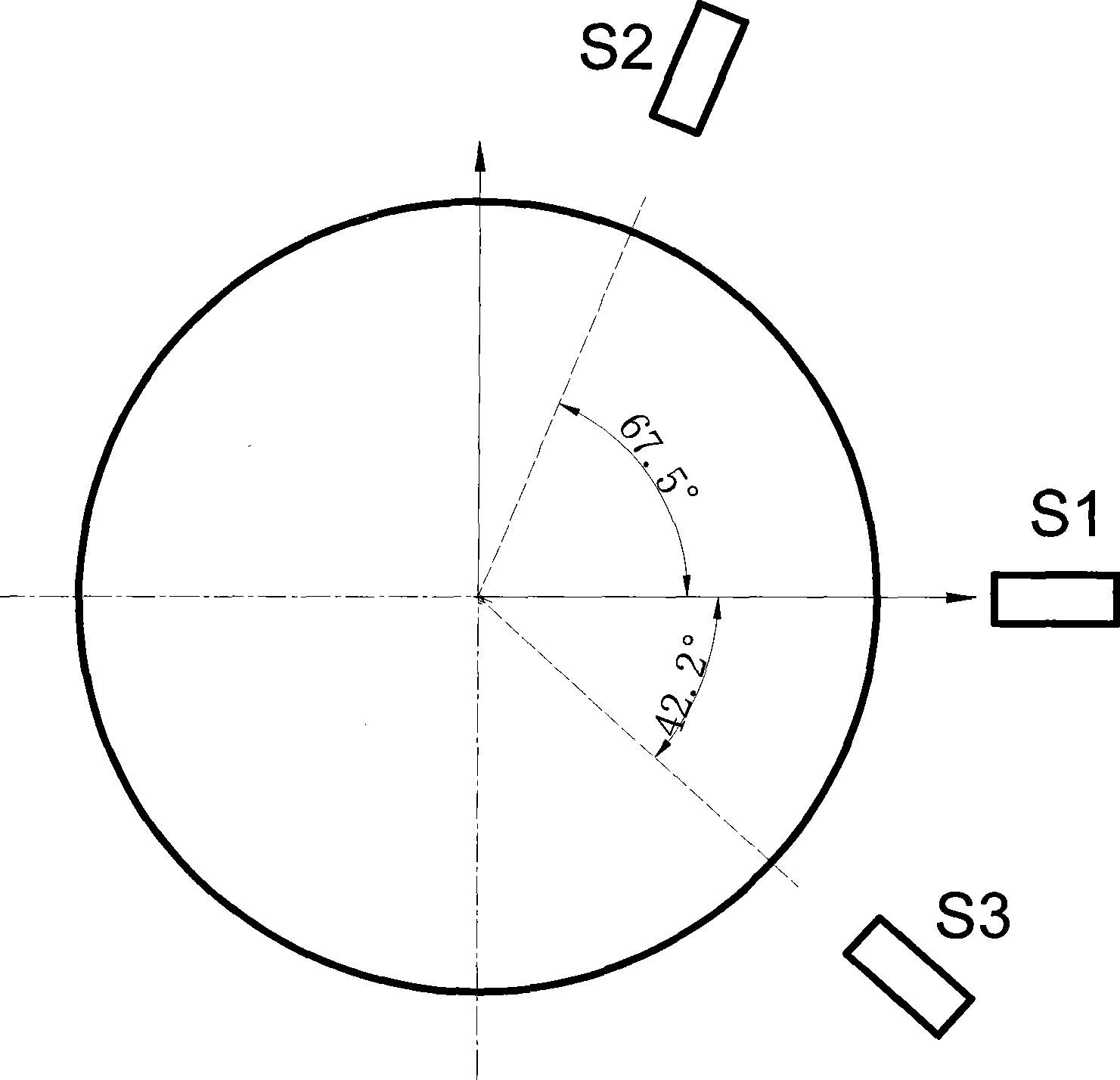
[0017] Such as figure 1 As shown, the present invention arranges three laser displacement sensors S1, S2, and S3 around the high-speed spindle, the positive angle between the first laser displacement sensor S1 and the second laser displacement sensor S2 is 67.5 degrees, and the first laser displacement sensor The negative angle between S1 and the third laser displacement sensor S3 is 42.2 degrees.

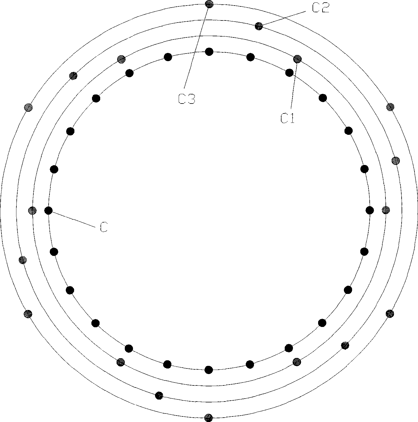
[0018] Such as figure 2 As shown, C is the point to be sampled, a total of n. C1, C2 and C3 are the sampling points when the spindle rotates the first, second and third revolutions respectively.

[0019] An angle encoder with line number N is installed on the main shaft, and the angle encoder is connected with the counting circuit. Due to the requirement of the three-point measurement method, it is necessary to sample the displacement of n (n can be divisible by N) points uniformly arranged in the circumferential direction of the main axis, and the angle between adjacent sampli...


PUM


Abstract

The invention discloses a method for detecting radial motion error of a high-speed principal axis by adopting a multi-circle superposition three-point method. Three laser displacement sensors are distributed around the high-speed principal axis which is provided with an angle encoder that has N lines and is connected with a scaling circuit; when the scaling circuit counts for Z times in an accumulating way and Z can not be divided exactly by N, the scaling circuit outputs sampled signals, and a trigger sensor implements sampling once; by repeating in this way, the principal axis is evenly distributed with n points for sampling by rotating the principal axis for a plurality of times to complete a sampling period; after every time of sampling, the sampling value is transmitted to an industrial computer through a USB interface and is then recorded; according to the requirements of detection accuracy, the sampling work having a plurality of sampling periods is carried out, the average sampling value of n points of every laser displacement sensor is calculated, and the deviation from circular form, the eccentric error and radial turning error of the principal axis which are obtained by separation are calculated. The method is not sensitive to the performance of the laser displacement sensor and is suitable for detecting radial motion error of the high-speed principal axis.

Description

technical field [0001] The invention relates to a spindle radial error detection technology, in particular to a method for detecting the radial motion error of a high-speed spindle by a multi-circle overlapping three-point method. Background technique [0002] High speed and high precision are one of the main development directions in the field of CNC machine tools. High-speed machining is a high-tech developed vigorously in the late 1990s. Now it has been widely used in industrialized countries and achieved extremely significant economic benefits. High-speed machining not only has extremely high production efficiency, but also can significantly improve the machining accuracy and surface quality of parts due to the substantial reduction of cutting force and the rapid removal of cutting heat. The cutting speed and feed speed of high-speed machining are 5-10 times higher than the conventional speed. In foreign machining centers, the spindle speed has reached 12000r / min~20000...

Claims


Application Information

Patent Timeline
IPC IPC(8): G01B11/00G01B11/24G01B11/27B23Q17/00B23Q17/24
Inventor 傅建中贺永黄斌
Owner ZHEJIANG UNIV
Why Eureka
Try Eureka