High wind speed smoke display method and device thereof

A display method and high wind speed technology, applied in the field of aerospace experiments, can solve the problems of high equipment cost, difficult experiment and heavy workload, and low Reynolds number in flow field display experiments, so as to improve high wind speed resistance and improve visibility The effect of reliability, accuracy and credibility

Inactive Publication Date: 2009-05-06
BEIHANG UNIV
View PDF0 Cites 17 Cited by
  • Summary
  • Abstract
  • Description
  • Claims
  • Application Information

AI Technical Summary

Problems solved by technology

Due to the limitation of the development level of the smoke line display experiment technology (generally, the Reynolds number of the flow field display experiment is low), the flow field/aerodynamic correlation is not at the same Reynolds number. For the high wind speed smoke display/aerodynamic (pressure ) measurement integrated experimental technology research, has not yet been carried out in China
In addition, although the digital particle image velocimetry system (DPIV) widely used in wind tunnels at home and abroad can quantitatively measure the flow field at relatively high wind speeds and obtain more detailed cross-sectional flow field distribution characteristics, experience has shown that particles The image velocimetry system is not only difficult to obtain a large-scale full flow field structure picture, and cannot realize the overall cognition and comprehensive under

Method used


Image

  • High wind speed smoke display method and device thereof
  • High wind speed smoke display method and device thereof
  • High wind speed smoke display method and device thereof

Examples


Embodiment Construction

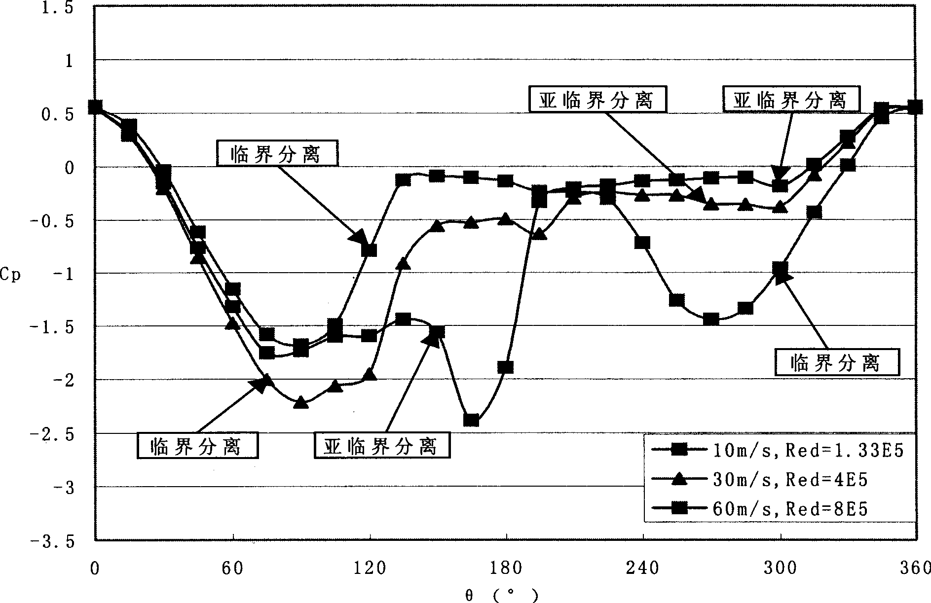
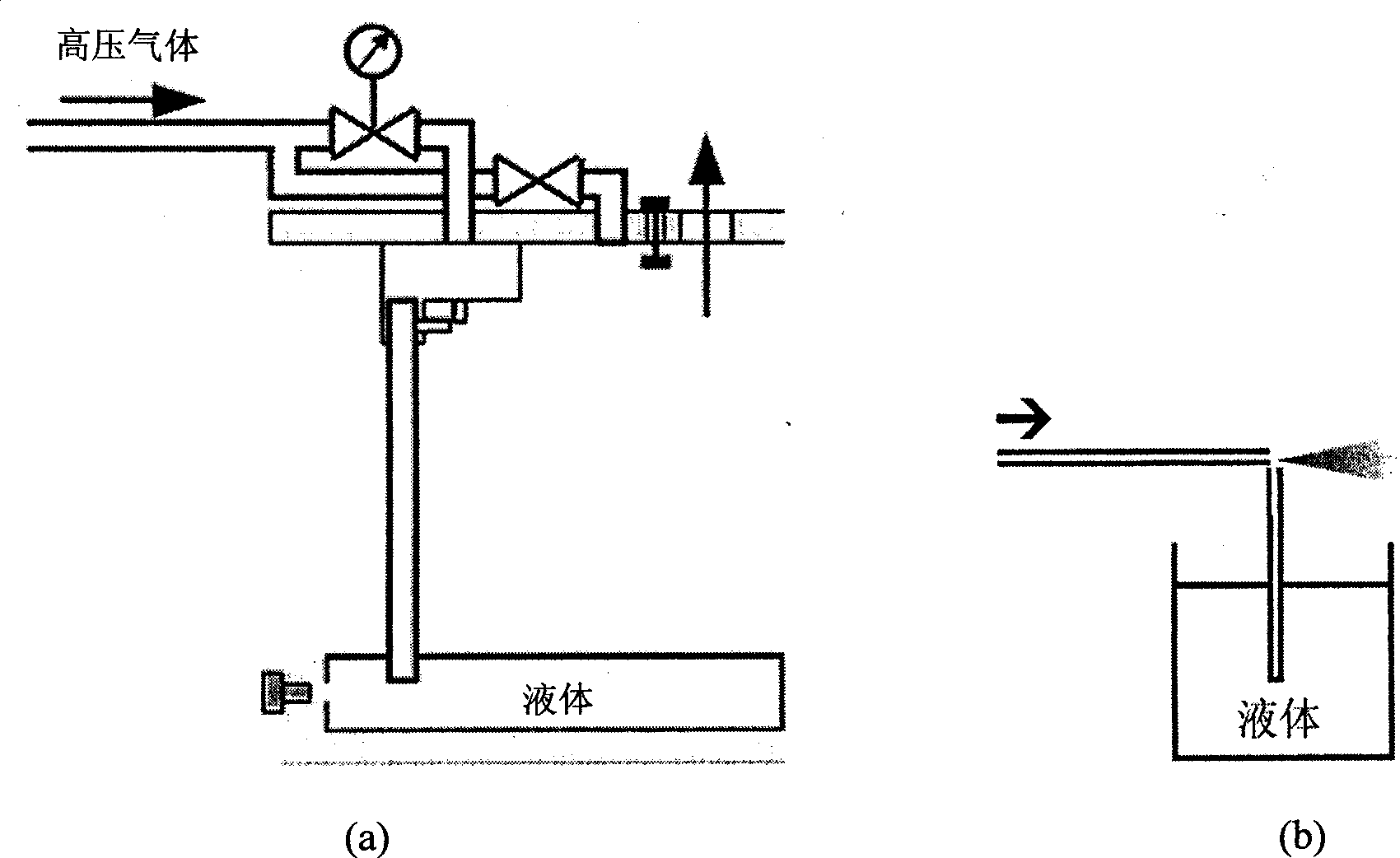
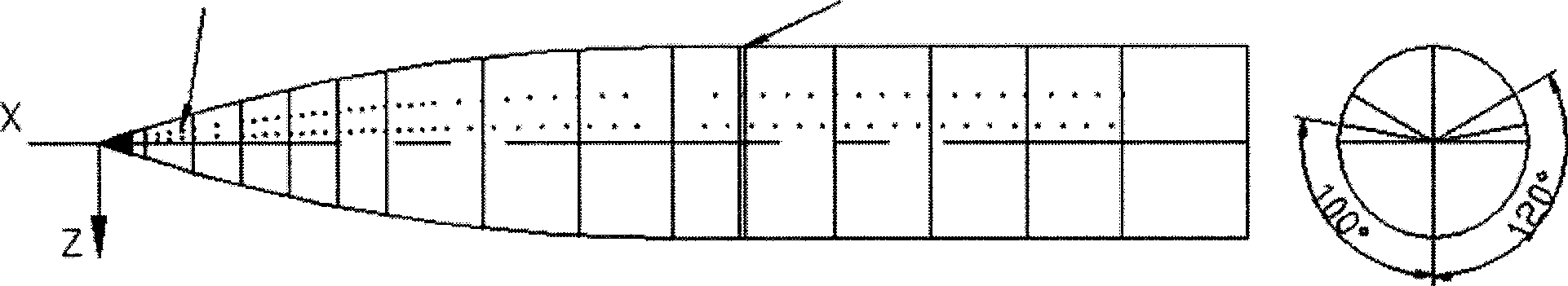
[0046] The present invention is a high-speed smoke display technology. On the basis of developing advanced smoke particles and smoke generators, smoke diversion holes are set on the slender and slender model body, which changes the traditional flow display experiment. In the way of particles, a clear laser sheet light display image was obtained under the experimental conditions of high wind speed (v=60m / s), and the quantitative measurement of the spatial vortex of the flow field was realized through the position pre-calibration technology. In addition, by setting a pressure monitoring ring, the influence of factors such as smoke injection mode and smoke injection pressure on the flow field display results can be monitored, thereby ensuring the accuracy of the flow field display. This smoke display technology and simple vortex quantitative measurement technology provide a key technical platform for the research on the Re number of slender bodies in low-velocity conventional wind...


PUM

PropertyMeasurementUnit
Diameteraaaaaaaaaa

Abstract

The invention relates to a method and a device for displaying smoke at a high wind speed. The method comprises the following steps: (a) manufacturing and preparing the device, (b) displaying a flow field, (c) monitoring pressure, (d) recording the flow field, and (e) quantifying the flow field. The device comprises a smoke injecting device A and a flow filed recording device B, wherein the smoke injecting device comprises an air compressor, a smoke generator, a smoke injecting pipeline, a model, a smoke shunt hole, a laser and an image recording device. Firstly, laser beams with a beam diameter smaller than 5mm are emitted by an argon ion CW (Continuous Wave) laser and are transformed into sheet beams by a cylindrical lens so as to provide high-intensity irradiation for the displayed flow field, and then the image recording device controlled by a computer is adopted for automatically shooting and recording structural images of the flow field. The invention adopts advanced technologies of injecting, displaying, recording and quantifying the smoke at the high wind speed and enables the test wind speed displayed by the smoke to reach 60m/s or higher and to be continuously displayed so as to provide necessary technological means for researching the complex detouring flows with high angles of attack and the Red (Reynolds) number effects of a slender body of revolution and an aircraft.

Description

(1) Technical field: [0001] The invention relates to a method and a device for displaying high wind speed smoke, belonging to the aerospace experiment technology. (two) background technology: [0002] Modern advanced aviation and aerospace weapons and equipment usually require high maneuverability and high agility, so the layout design has fully utilized the controllable separation flow and favorable and stable vortex flow in the flow around the high angle of attack and its corresponding favorable interference, thereby improving their flight performance. Therefore, in the process of aerodynamic layout research and design of modern aircraft, the flow display technology in wind tunnel and water tunnel experiments is fully utilized to display its complex flow structure and further reveal its complex interference flow mechanism and corresponding main control parameters. become one of the important research tools. [0003] The advanced fighters currently in service and under de...

Claims


Application Information

Patent Timeline
IPC IPC(8): G01M9/00
Inventor 邓学蓥王延奎柏楠董超马宝锋李岩
Owner BEIHANG UNIV
Why Eureka
Try Eureka