
Dynamic data collection system and accurately positioning method for collection position

A technology of dynamic data acquisition and data acquisition, which is applied in control systems, motor generator control, electrical components, etc., can solve the problems of uneven motor drive pulse cycle, increased system design complexity, and collected data jitter, etc., and achieves low cost. , strong real-time, stable operation effect

Active Publication Date: 2009-05-06
SHENZHEN MINDRAY BIO MEDICAL ELECTRONICS CO LTD
View PDF0 Cites 16 Cited by
  • Summary
  • Abstract
  • Description
  • Claims
  • Application Information

AI Technical Summary

Problems solved by technology

[0003] The above-mentioned method of direct stepping motor pulse positioning is controlled by software. Due to the uncertainty of software execution time, the motor drive pulse cycle will be uneven, and the motor will move fast and slow.
At the same time, the collection point will also change with the software execution time, resulting in the jump of the collected data
The positioning method of the shaft angle encoder improves the positioning accuracy of the collection point, but still has all the disadvantages of software control; and additional encoders are required, which increases the complexity of the system design and significantly increases the cost

Method used


Image

  • Dynamic data collection system and accurately positioning method for collection position
  • Dynamic data collection system and accurately positioning method for collection position
  • Dynamic data collection system and accurately positioning method for collection position

Examples


Embodiment Construction

[0019] The present invention will be described in further detail below through specific embodiments and in conjunction with the accompanying drawings.

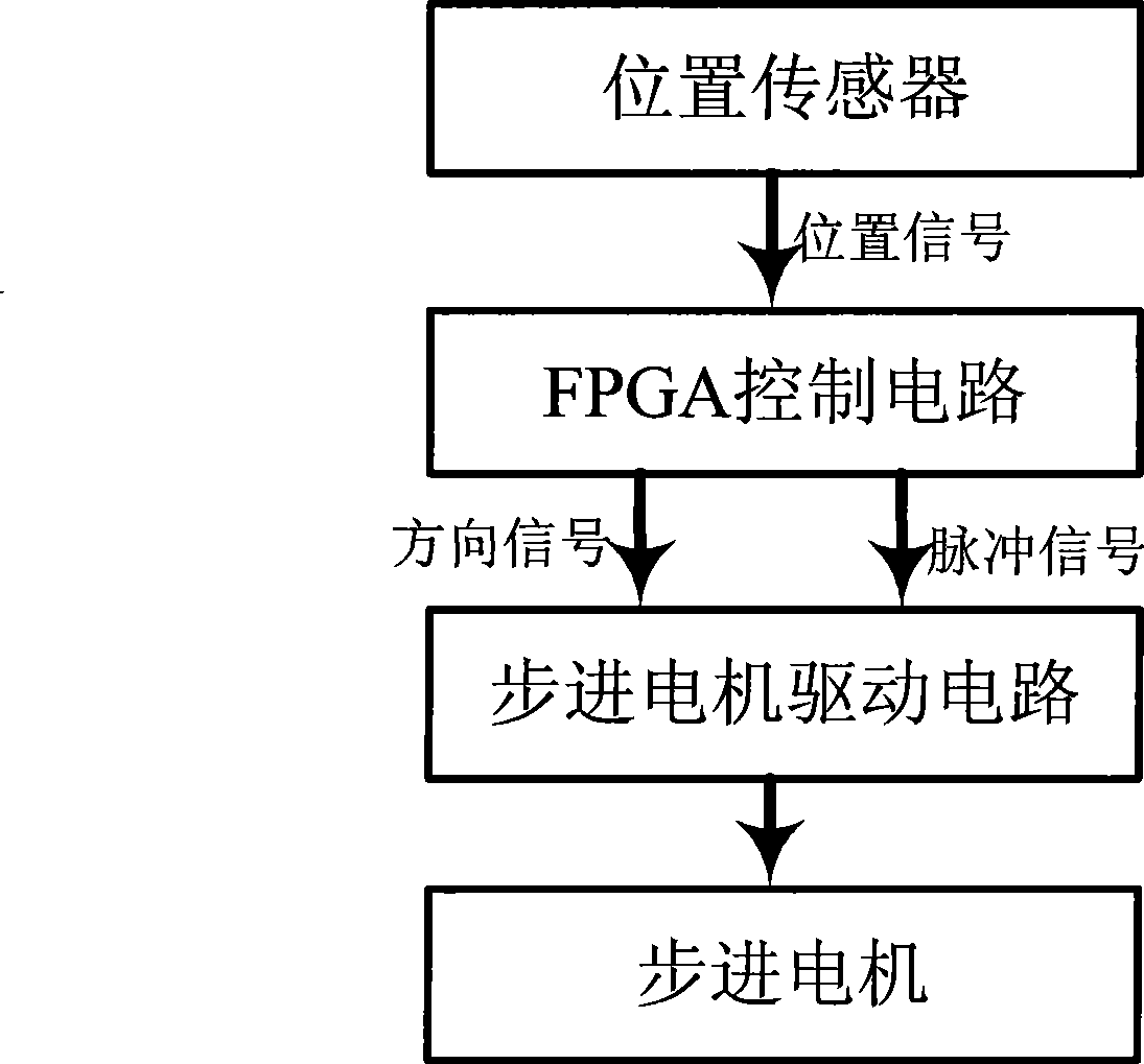
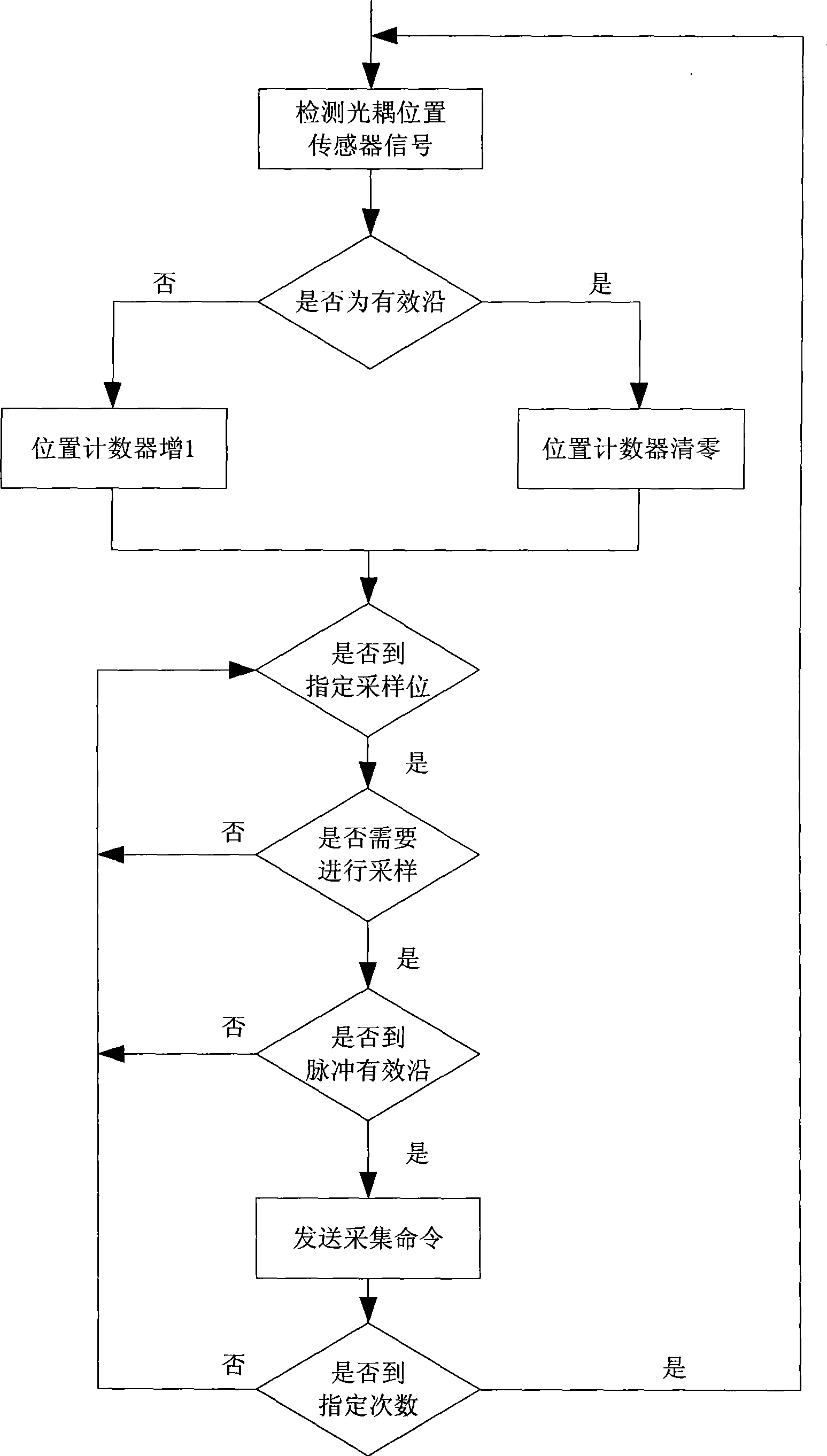
[0020] The principle block diagram of the collection point positioning system in this example is as follows: figure 1 Shown, including FPGA control circuit, stepper motor, stepper motor drive circuit and position sensor. The FPGA control circuit includes logic modules such as stepper motor motion control module, acquisition point positioning module and data acquisition module, and position counters; the stepper motor motion control module sends direction and pulse signals to the stepper motor drive circuit, and maintains the position counter . The stepping motor drive circuit drives the stepping motor to move after receiving the pulse and direction signals sent by the FPGA control circuit. During the movement of the stepper motor, the acquisition point positioning module of the FPGA control circuit detects the signal of the ...


PUM


Abstract

The invention discloses a dynamic data acquiring system and a method for precisely positioning an acquiring position thereof. The dynamic data acquiring system comprises an FPGA controller, a step motor, a driving circuit of the step motor, and a position sensor. An FPGA controlling circuit sends direction and pulse signals to the driving circuit of the step motor and maintains a position counter. The driving circuit of the step motor receives driving pulses and direction signals and drives the step motor to move. In the moving process of the step motor, when the FPGA detects that the position sensor has the effective jump, the FPGA resets the position counter, and the position counter counts the sent pulses; after a sent pulse number reaches the set position pulse number of acquiring points and the effective condition of the pulses is detected, the data acquiring operation is carried out. The invention has the advantages of accurate positioning of the acquiring points, high real-time performance, automatic control, simplicity, reliability and lower cost.

Description

【Technical field】 [0001] The invention relates to positioning control in data collection, in particular to a positioning method therein. 【Background technique】 [0002] In the positioning of the stepper motor, for example, in a photometer that uses a filter wheel to achieve colorimetric measurement, the stepper motor drives the filter wheel to move, and it needs to be collected at a specified position during the movement to obtain measurement data. The accuracy of the location of the collection point directly determines the accuracy and repeatability of the measurement data. At present, in the application of data acquisition during the movement of the stepping motor, the location of the acquisition point mainly adopts the following methods: 1. Positioning directly through the pulse number of the stepping motor: a controller is used in the system to send a pulse signal to the drive circuit to drive the stepper motor. The motor moves, and a counter is maintained inside the co...

Claims


Application Information

Patent Timeline
Patent Type & Authority Applications(China)
IPC IPC(8): H02P8/14H02P8/34G05D3/12
Inventor 赵背生赵云翁彦雯
Owner SHENZHEN MINDRAY BIO MEDICAL ELECTRONICS CO LTD
Learn More