Plumbago melting furnace

A melting furnace and graphite technology, applied in the field of melting furnaces, can solve the problems of low production efficiency, short service life of carbon steel furnaces, poor uniformity of material mixing and ejection, etc., and achieve the effects of reducing processing time, increasing service life and reducing labor intensity

Inactive Publication Date: 2009-05-13
江苏金杨科技有限公司
View PDF0 Cites 2 Cited by
  • Summary
  • Abstract
  • Description
  • Claims
  • Application Information

AI Technical Summary

Problems solved by technology

The former is manually operated and completed entirely by experience. The uniformity and stability of the product are poor, and the operating environment is harsh, and the labor intensity of the operator is high.
The latter has the following defects: First, because the carbon steel furnace is easily corroded by the alkaline substances in the material when heated, the inner wall of the high-temperature chamber is corroded and peeled off, and the peeled corrosion products fall into the material, which not only greatly increases the iron content of the semi-finished product , increase the processing time of the subsequent purification process and the consumption of processing chemicals, and lead to a very short service life of the carbon steel furnace, which generally needs to be replaced once every half a year; Only the auger can be used, and the mixing and pushing uniformity of the materials are poor; the third is that after the high-temperature materials are stirred out of the melting furnace, most of them are naturally cooled to room temperature, and then purified by chemical agents
The temperature of high-temperature materials after being baked is generally around 700°C, and a large amount of heat is dissipated in the workplace, which not only deteriorates the operating environment, but also adopts natural cooling, which has slow cooling speed and low production efficiency.

Method used


Image

  • Plumbago melting furnace
  • Plumbago melting furnace

Examples


Embodiment 1

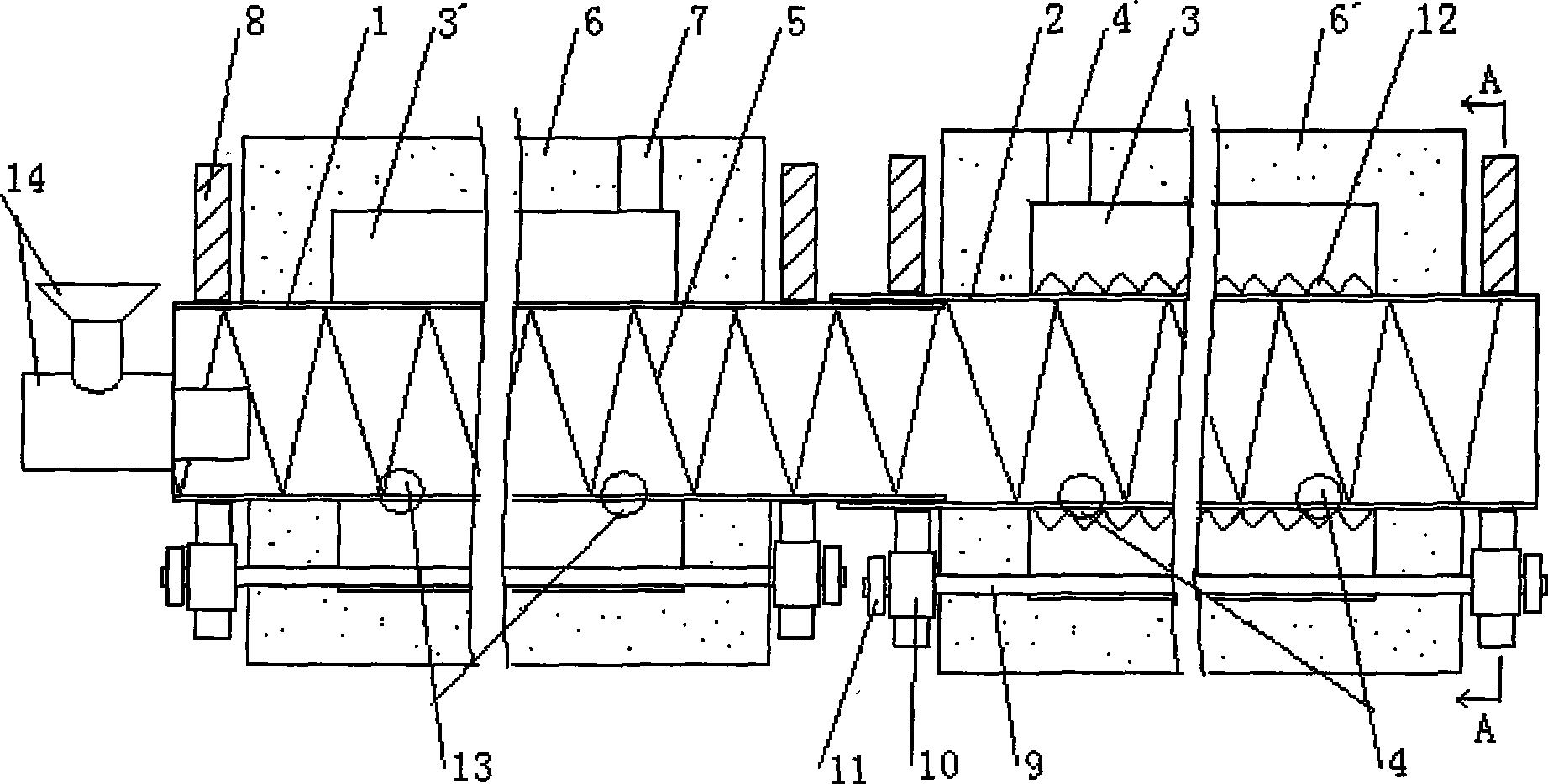
[0018] like figure 1 As shown, the present invention includes a transmission device, a high-temperature chamber, and a stirring and ejecting device for materials in the high-temperature chamber, as well as an insulating layer 6 of the high-temperature chamber, and a heating chamber 3' between the two.

[0019] still as figure 1 As shown, the high temperature chamber 1 is made of stainless steel, a metal material resistant to high temperature and alkali corrosion. The material stirring and pushing device is that the inner wall of the high temperature chamber 1 is provided with spiral fins 5, and the horizontal angle of the spiral fins 5 is selected as 50°. The spiral fin 5 is made of the same material as the high-temperature chamber 1 , and the spiral fin 5 is processed into a strip-shaped sheet, and one side thereof is welded to the inner wall of the high-temperature chamber 1 . The transmission shaft 9 in the transmission device passes through the insulation layer 6 of the ...

Embodiment 2

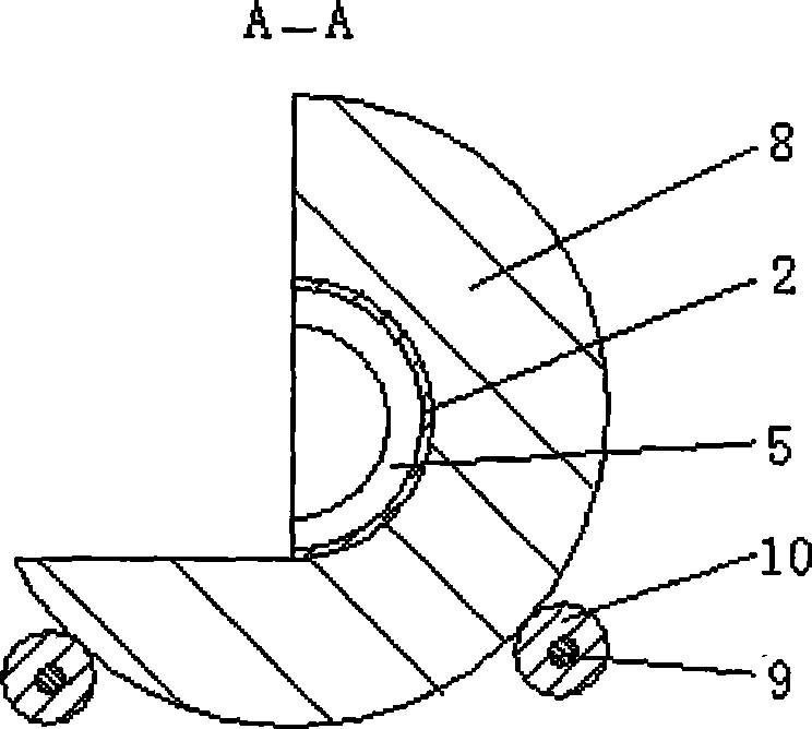
[0021] like figure 1 As shown, the high temperature chamber 1 is connected with the cooling chamber 2, the inner diameter of the high temperature chamber 1 is slightly smaller than the inner diameter of the cooling chamber 2, and its discharge end is inserted into the feeding end of the cooling chamber 2, and the two are connected by a clearance fit. The cooling chamber 2 is provided with a transmission device consistent with the high-temperature chamber 1, and the cooling chamber 2 is also provided with an insulation layer 6'; the transmission shaft 9 in the transmission device passes through the insulation layer 6' of the cooling chamber 2 at both ends, and adopts The bearing is movably connected on the frame (not shown in the figure); the transmission wheel 10 is fixedly connected to the two ends of the transmission shaft 9 respectively, and the end of the transmission shaft 9 outside the transmission wheel 10 is respectively fixedly connected with a power input wheel 11, T...


PUM


Abstract

The invention discloses a graphite melting furnace which comprises a transmission device, a heating chamber, an insulating layer in the heating chamber, and material stirring and pushing devices in the heating chamber. The heating chamber is made of corrosion and high temperature resistant metal materials; and the material stirring and pushing devices adopt the structure that a helical fin is arranged on the inner wall of the heating chamber. The invention further adopts the improved scheme that the discharge end of the heating chamber is communicated with a cooling chamber. Due to the heating chamber made of high temperature resistant stainless steel materials, the inner surface of the high temperature chamber can not be corroded by material, and corrosives can not fall into the material, so that the processing time of the next purification procedure is reduced, the dosage of purifying medicines is saved, and the service life of the melting furnace is particularly prolonged. The graphite melting furnace is provided with the cooling chamber, and has the advantages of quick cooling speed and high production efficiency; and meanwhile, the invention greatly improves the operating environment and reduces the labor intensity of operators.

Description

Technical field: [0001] The present invention relates to the purification of graphite, in particular to a melting furnace in the melting process for improving the purity of graphite. Background technique: [0002] At present, in the melting process of graphite purification, some methods are manually stirred under heating conditions, and some are carried out in carbon steel furnaces equipped with augers. Because the former is manually operated, it is completed entirely by experience, the uniformity and stability of the product are relatively poor, and the operating environment is harsh, and the labor intensity of the operator is high. The latter has the following defects: First, because the carbon steel furnace is easily corroded by the alkaline substances in the material when heated, the inner wall of the high-temperature chamber is corroded and peeled off, and the peeled corrosion products fall into the material, which not only greatly increases the iron content of the semi...

Claims


Application Information

Patent Timeline
Patent Type & Authority Applications(China)
IPC IPC(8): C01B31/04
Inventor 叶厚理柳依玲徐大为
Owner 江苏金杨科技有限公司
Why Eureka
Try Eureka