
Method and device for operating spinning machine with free end rotor

A rotor spinning, free-end technology, which is applied in the directions of free-end spinning machines, spinning machines, and continuously wound spinning machines, to achieve the effect of reducing energy consumption

Active Publication Date: 2009-05-13
ZHUOLANG INTELLIGENT MACHINERY CO LTD
View PDF4 Cites 9 Cited by
  • Summary
  • Abstract
  • Description
  • Claims
  • Application Information

AI Technical Summary

Problems solved by technology

[0014] However, the following embodiments of the semi-automatic open-end rotor spinning machine have the disadvantage that the switch for actuating the second vacuum source is arranged on the end frame or on the drive frame of the spinning machine

Method used


Image

  • Method and device for operating spinning machine with free end rotor
  • Method and device for operating spinning machine with free end rotor

Examples


Embodiment Construction

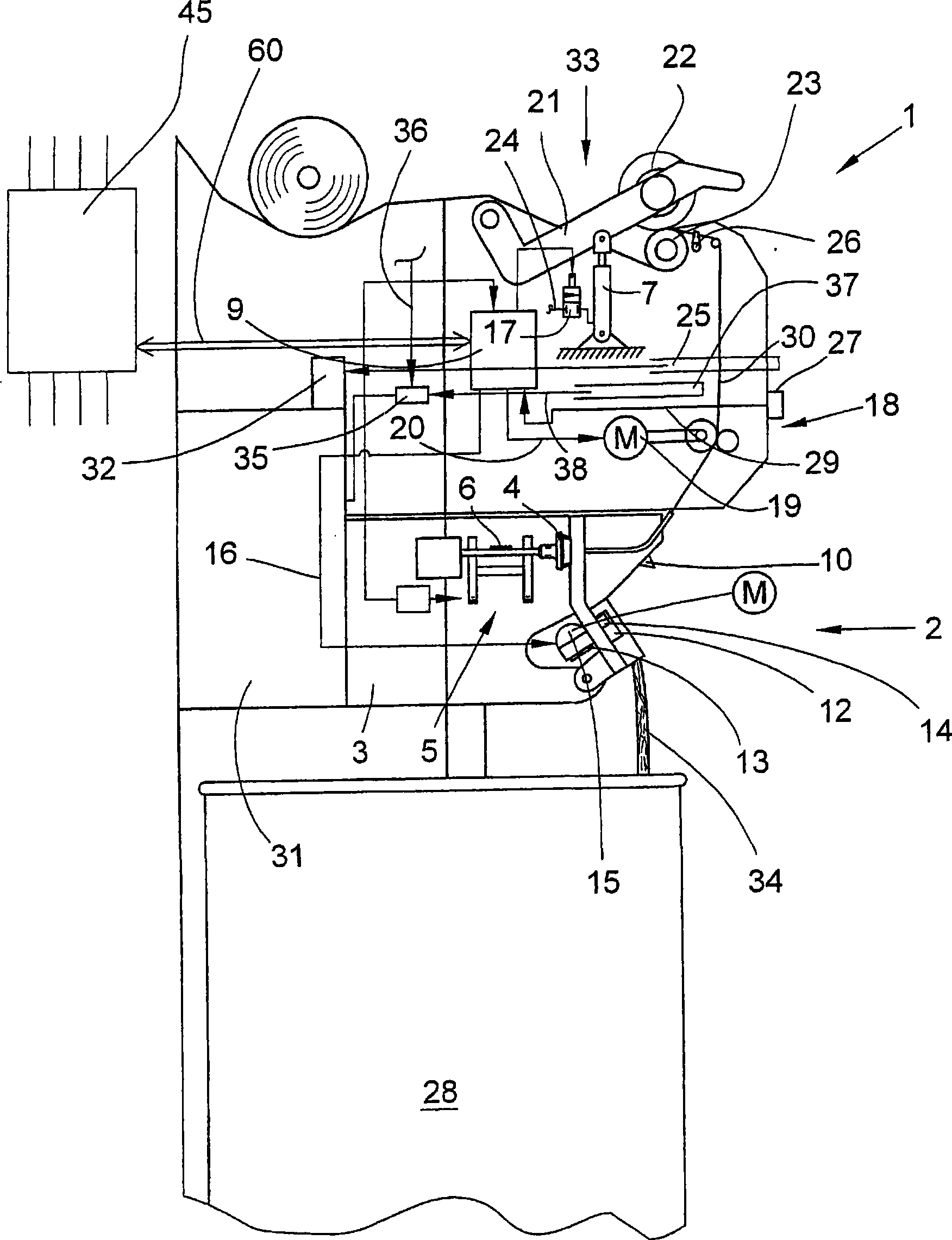
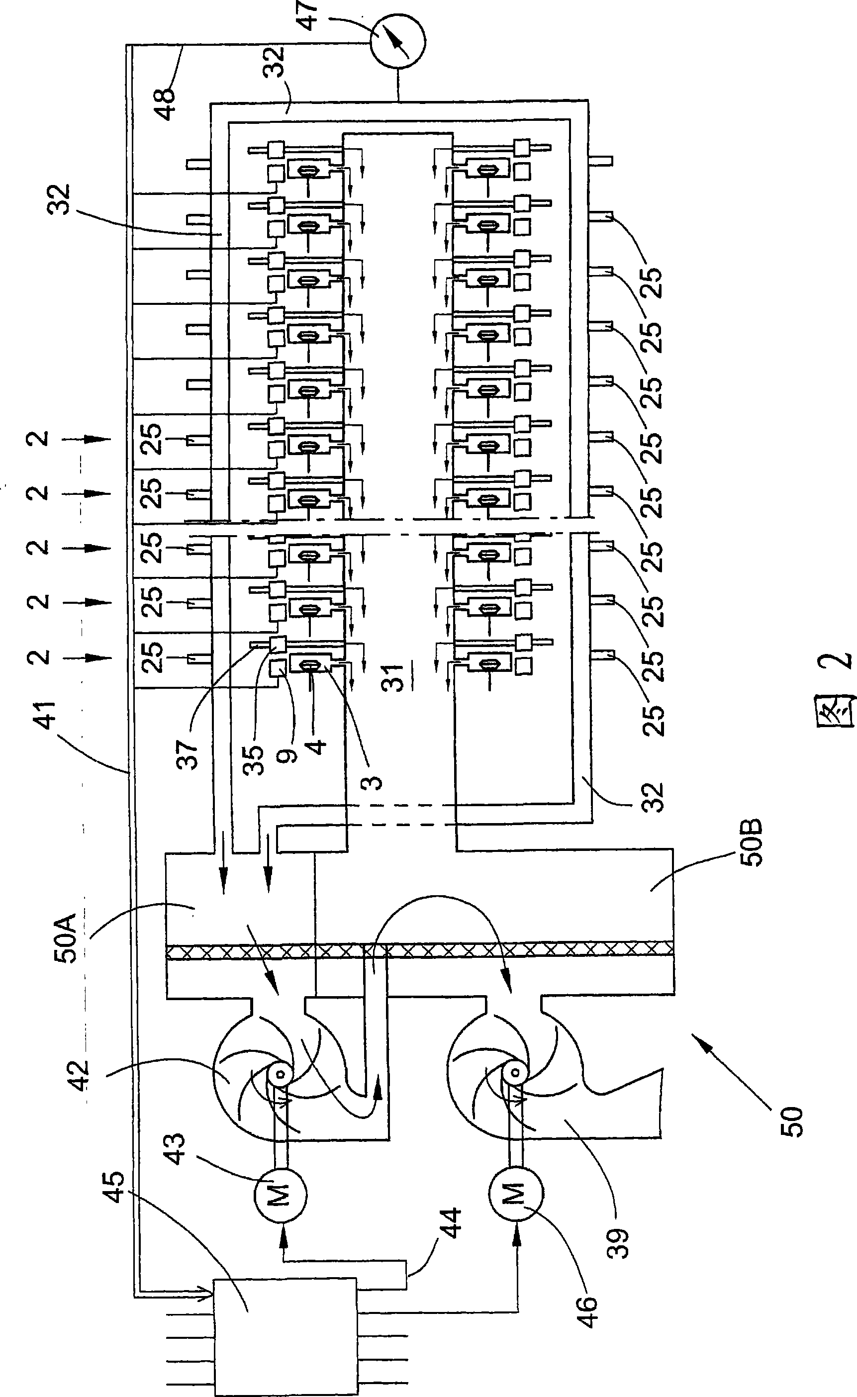
[0031]figure 1 The semi-automatic open-end rotor spinning machine 1 shown in has a plurality of stations 2 which are each equipped with a spinning device 3 and a winding mechanism 33 . The fiber strip 34 provided in the spinning drum 28 is correspondingly spun into a yarn 30 in the spinning device 3 , and the yarn 30 is subsequently wound into a cross-wound bobbin 22 on a winding device 33 .

[0032] Here, the winding mechanism 33 respectively has: a creel 21 for rotatably holding the sleeve of the cross-wound bobbin 22; bobbin drive roller 23; Lifting mechanism 7 for cross-winding bobbin 22. The lifting mechanism 7 is configured as a thrust piston drive and is connected to a (not shown) overpressure source, for example via a pneumatic line 24 in which a solenoid valve 17 is connected. Furthermore (not shown) a braking mechanism (not shown) is arranged in the region of the winding mechanism 33 , by means of which, if necessary, free rotation of the cross-wound bobbin 22 lifte...


PUM


Abstract

The invention relates to a method and device for operating a free end rotor spinner which comprises a plurality of work stations having a spinning device for producing yarns and a winding device for producing a cross winding bobbin, wherein the free end rotor spinner comprises a central control unit and a negative pressure system for the spinner, the negative system also comprises a second negative pressure source which can be turned on when needed besides a main negative pressure source. In the station region, a yarn storage spout subjected with negative pressure for receiving a yarn quantity required in connection with a spinning process and a suction nozzle subjected with the negative pressure which is used during a cross coil / empty case replacement are respectively arranged. According to the invention, the second negative pressure source (42) is arranged to be automatic turn-on as occasion requires.

Description

technical field [0001] The invention relates to a method for operating an open-end rotor spinning machine according to the preamble of the first aspect and a device according to the fifth aspect. Background technique [0002] Open-end rotor spinning machines with a plurality of workstations of the same type, a central control unit and a vacuum system specific to the textile machine are known in various, sometimes very different, embodiments and are described exhaustively in the patent literature. [0003] On the stations of such a textile machine, the fiber strips provided preferably in the spinning drums are spun into yarns by means of an open-end spinning device, and the yarns are then wound into cross-wound bobbins on a winding device. However, there are sometimes considerable differences between the various open-end rotor spinning machines in terms of their design structure and their mode of operation. [0004] For example, DE 198 36 065 A1 discloses an open-end rotor s...

Claims


Application Information

Patent Timeline
Patent Type & Authority Applications(China)
IPC IPC(8): D01H4/50D01H4/00D01H9/02
CPCD01H4/50D01H11/00
Inventor 拉尔夫·西韦特德特勒夫·舍尔特黑里贝特·梅尔滕斯
Owner ZHUOLANG INTELLIGENT MACHINERY CO LTD
Learn More