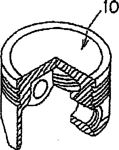
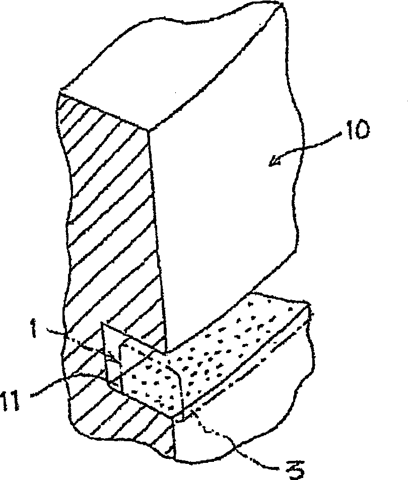
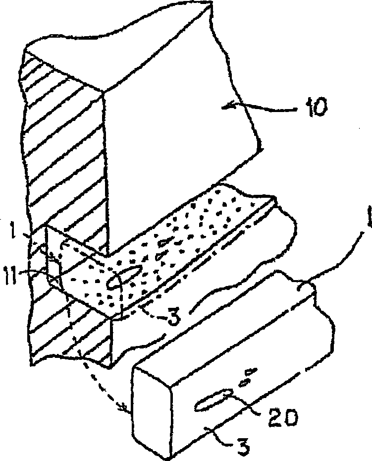
Piston ring

A technology for piston rings and base layers, applied in the field of piston rings, can solve the problems of surface coating film wear and peeling, loss of lubricating ability, wear of piston ring grooves, etc., and achieve the effect of preventing peeling

Inactive Publication Date: 2009-05-13
NIPPON PISTONRING CO LTD +1
View PDF3 Cites 10 Cited by
  • Summary
  • Abstract
  • Description
  • Claims
  • Application Information

AI Technical Summary

Problems solved by technology

However, with this method, there may be no problem at the initial stage when the surface coating film has sufficient lubricating ability, but after a long time, the surfa

Method used


Image

  • Piston ring
  • Piston ring
  • Piston ring

Examples


Embodiment Construction

[0041] Refer below Image 6 and FIG. 7 present a first embodiment of a piston ring according to the invention.

[0042] refer to Image 6 , the piston ring 60 of this embodiment has a piston ring body 61 and on at least one of the upper surface and the lower surface of the piston ring body 61 ( Image 6 In is the surface coating film 62 formed on both the upper surface and the lower surface). The surface coating film 62 is provided on the portion of the piston ring body 61 farthest from the sliding surface side, and is composed of an outermost surface layer 64 including a heat-resistant resin 65 and a base (innermost) layer 63 . The metal powder 67 contained in the heat-resistant resin 65 , the base layer 63 is disposed closest to the piston ring body 61 and is composed of the heat-resistant resin 66 .

[0043] The material of the piston ring body 61 of the present invention is not particularly limited, and various materials can be used. For example, steel (steel material)...


PUM

PropertyMeasurementUnit
Average particle diameteraaaaaaaaaa

Abstract

A piston ring includes a piston ring body and a surface coating film formed on at least one of upper and lower surfaces of the piston ring body. The surface coating film has a most outside surface layer including a heat-resistant resin and a metal powder contained in the heat-resistant resin and a base bottom layer formed nearest the piston ring body and including a heat-resistant resin. The base bottom layer may also include a metal powder.

Description

technical field [0001] The present invention relates to a piston ring for an internal combustion engine, and more particularly, to a piston ring capable of effectively preventing aluminum from adhering (depositing) to the piston ring. Background technique [0002] Typically, a compression ring and an oil ring are mounted to a reciprocating piston as a set of piston rings. The compression ring has the function of preventing the blow-by phenomenon in which the high-pressure combustion gas is ejected from the combustion chamber side to the crank chamber side. On the other hand, the oil ring is mainly used to realize the function of suppressing the oil-up phenomenon, which means that excessive lubricating oil adhering to the inner wall surface of the cylinder intrudes into the combustion chamber from the crank chamber side. side and is consumed immediately. Among the conventional standard combinations of piston rings, a three-ring combination is known, consisting of two compre...

Claims


Application Information

Patent Timeline
IPC IPC(8): F02F5/00F16J9/26
Inventor 仮屋智孝为贝悦夫石川裕三靏田诚
Owner NIPPON PISTONRING CO LTD
Why Eureka
Try Eureka