LED back light source structure

An LED backlight and LED chip technology, applied in the fields of optics and image processing, can solve the problems of increased energy consumption and heat, and achieve the effects of preventing deformation, improving light efficiency and uniformity

Inactive Publication Date: 2009-05-13
厦门顶昊显示技术有限公司
View PDF0 Cites 9 Cited by
  • Summary
  • Abstract
  • Description
  • Claims
  • Application Information

AI Technical Summary

Problems solved by technology

[0003] Since the LED backlight is a point light source, if you want to increase the brightness of the LED backlight, you must increase the number of

Method used


Image

  • LED back light source structure
  • LED back light source structure
  • LED back light source structure

Examples


Embodiment Construction

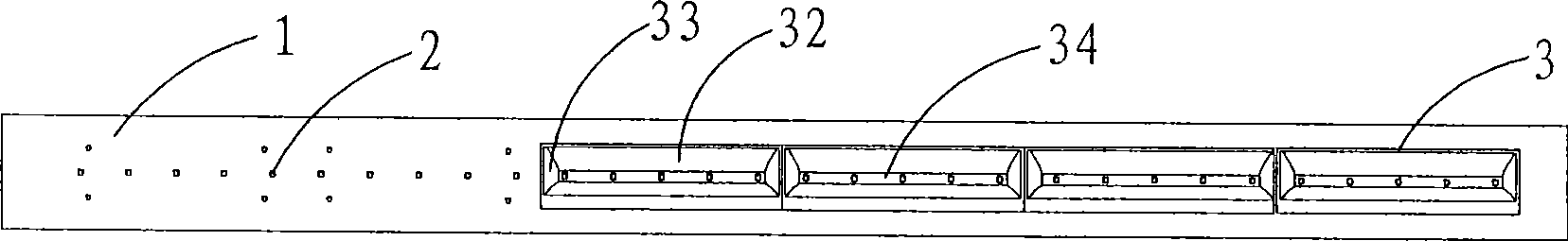
[0022] Such as Figure 1 to Figure 3 As shown, the LED backlight structure of the present invention includes a substrate 1 , a plurality of LED chips 2 and a plurality of reflective modules 3 .

[0023] The substrate 1 is a strip-shaped linear plate, and the LED chips 2 are arranged on the substrate 1 in a line;

[0024] Cooperate Figure 4 , 5 , 6, and 7, the reflective module 3 is a rectangular block formed in response to the size of the substrate 1, its upper end is an opening 31, and its front and rear inner surfaces are arc-shaped concaves from the upper end to the bottom to form an asymmetric curved surface 32 , and the left and right inner surfaces are also arc-shaped and concave from the upper end to the bottom to form an asymmetric curved surface 33, and the curvature of the asymmetric curved surfaces 32, 33 is set in response to the length and width of the light guide plate 4; A through linear groove 34 is formed below, and the linear groove 34 communicates with t...


PUM


Abstract

The invention discloses an LED backlight source structure, comprising a substrate and a plurality of LED chips, the LED chips are linearly arranged on the substrate; wherein, at least one rectangular reflective module is arranged on the substrate, the reflective module is covered on the LED chips, the various inner surfaces of the reflective module are arc-shaped concave surfaces, and the arc curvatures of each two opposite inner surfaces are different. The LED backlight source structure utilizes that the arc-shaped concave surfaces can directionally condense the light of the LED chips and can converge the light which is scattered to the outside by the LED to the direction which needs to irradiate by a backlight source, so that the LED backlight source structure can not only increase the irradiation distance of the light in an effective region, but also prevent the loss of the light in a non-effective light-emitting region of the backlight source, thus improving the luminous efficiency of the LED backlight source in the effective region and increasing the irradiation brightness of the backlight source in the effective region; in addition, the setting of the non-symmetric reflective curved surfaces can obtain the brightness which is needed by the distal edge of a large-sized backlight and ensure the uniformity of the light of the large-sized backlight during the unilateral incidence.

Description

technical field [0001] The invention relates to the field of optics and image processing of electronic equipment, in particular to an LED backlight structure applied to a liquid crystal display. Background technique [0002] The development of backlight can be traced back to World War II, when ultra-small tungsten filament lamps were used as the backlight of aircraft instruments. With the continuous development of liquid crystal display technology, the backlight source used in the liquid crystal display has the characteristics of high brightness, long life and uniform light emission. At present, there are mainly three types of backlight sources: EL, CCFL, and LED. According to the location of the light source, they are divided into side-lit and direct-lit. The most commonly used edge-lit types are LED backlight and CCFL backlight. With the continuous development of LCD modules in the direction of brighter, lighter and thinner, edge-lit CCFL backlights have become the mains...

Claims


Application Information

Patent Timeline
IPC IPC(8): F21V7/09F21V7/10G02F1/13357F21Y101/02G02F1/1335
Inventor 林瑞梅
Owner 厦门顶昊显示技术有限公司
Why Eureka
Try Eureka