Periodic scanning optical delay line based on inclined parabolic type bus helical face reflection mirror

A technology of optical delay lines and mirrors, applied in optics, optical components, mirrors, etc., can solve the problems of limiting the maximum delay range, difficult compensation and correction, and inconvenient testing, so as to facilitate the construction of delay lines, eliminate beam translation, increase The effect of large delay times

Inactive Publication Date: 2009-05-13
TIANJIN UNIV
View PDF1 Cites 17 Cited by
  • Summary
  • Abstract
  • Description
  • Claims
  • Application Information

AI Technical Summary

Problems solved by technology

However, through the theoretical analysis of differential geometry, it is found that this optical delay line has the following technical barriers: (1) The mirror surface of the optical delay line is a saddle surface, and the original plane wavefront reflected by the mirror is distorted into a saddle surface, And when the lift distance increases (corresponding to a larger time delay range) and the radius of gyration decreases, the saddle-shaped wavefront distortion becomes more serious, and the saddle-shaped optical wavefront distortion is complex curved surface wavefront phase distortion, which is difficult to compensate by conventional optical devices Correction; (2) The angle between the outgoing beam and the incident beam of the optical delay line depends on the distance between the lift of the helicoid and the incident point of the incident light from the axis of rotation. The included angle of the light b

Method used


Image

  • Periodic scanning optical delay line based on inclined parabolic type bus helical face reflection mirror
  • Periodic scanning optical delay line based on inclined parabolic type bus helical face reflection mirror
  • Periodic scanning optical delay line based on inclined parabolic type bus helical face reflection mirror

Examples


Embodiment Construction

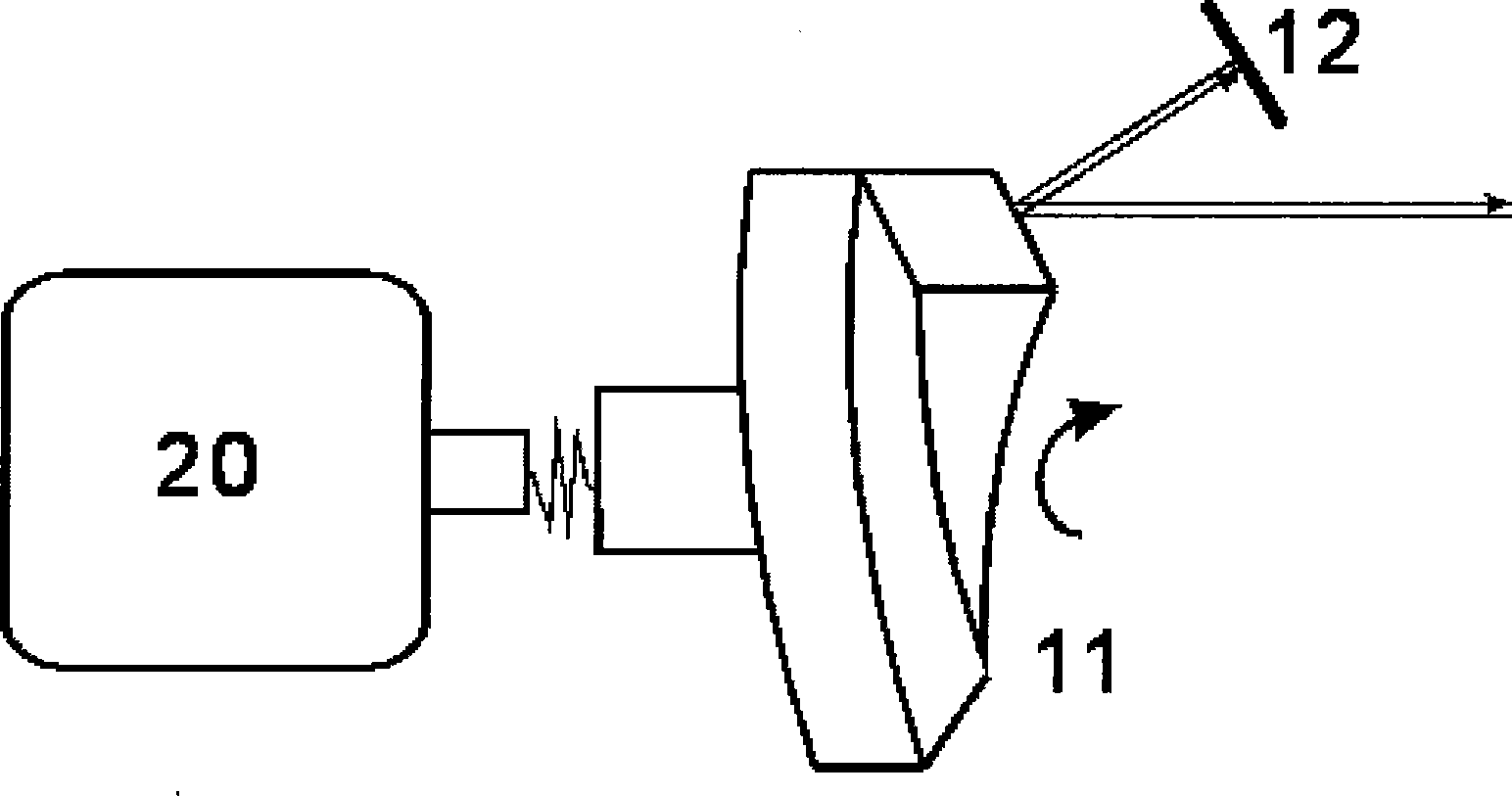
[0018] The specific implementation method of the present invention to obtain the periodic scanning optical delay line based on the inclined parabolic generatrix helicoid reflector is as follows:

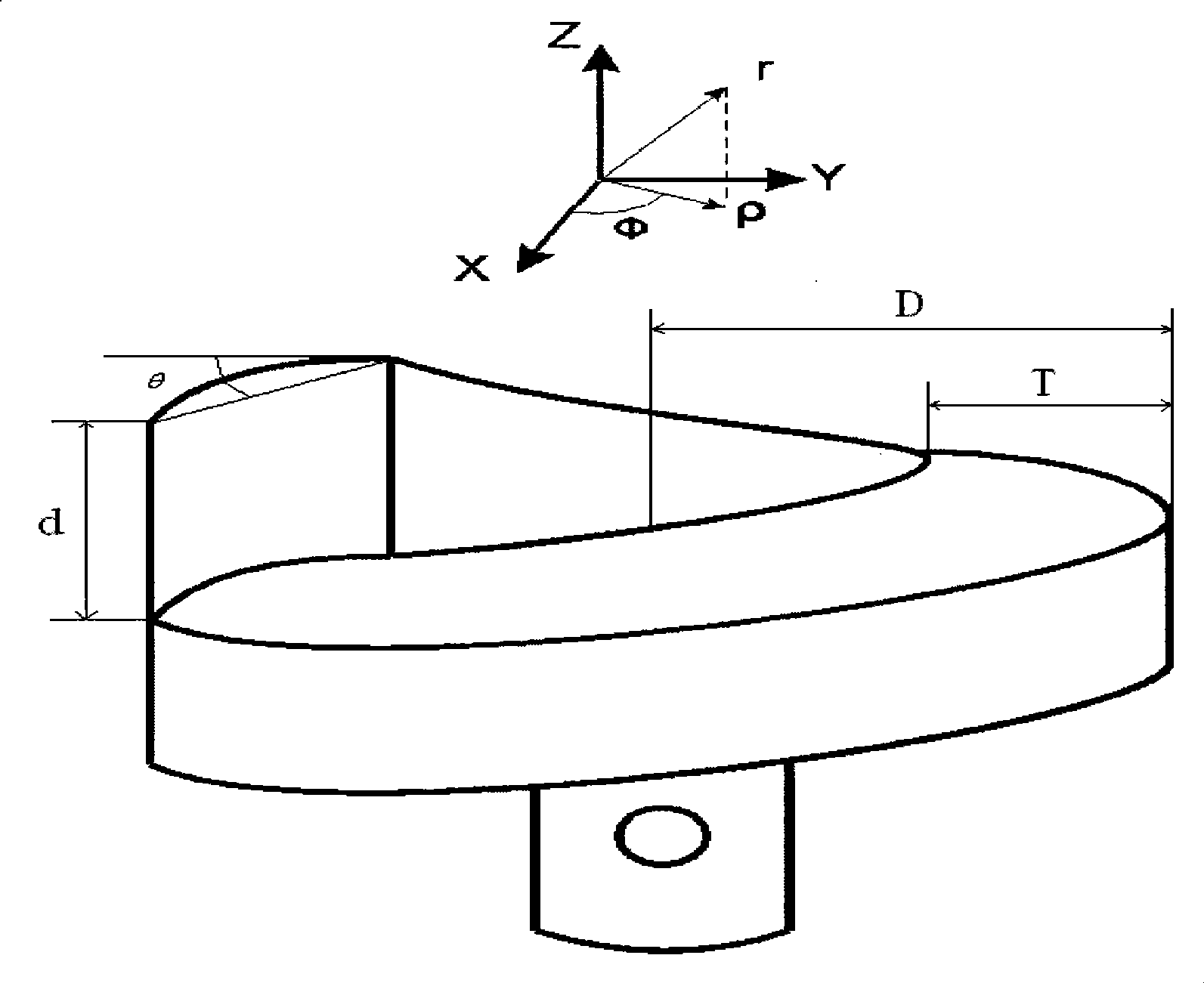
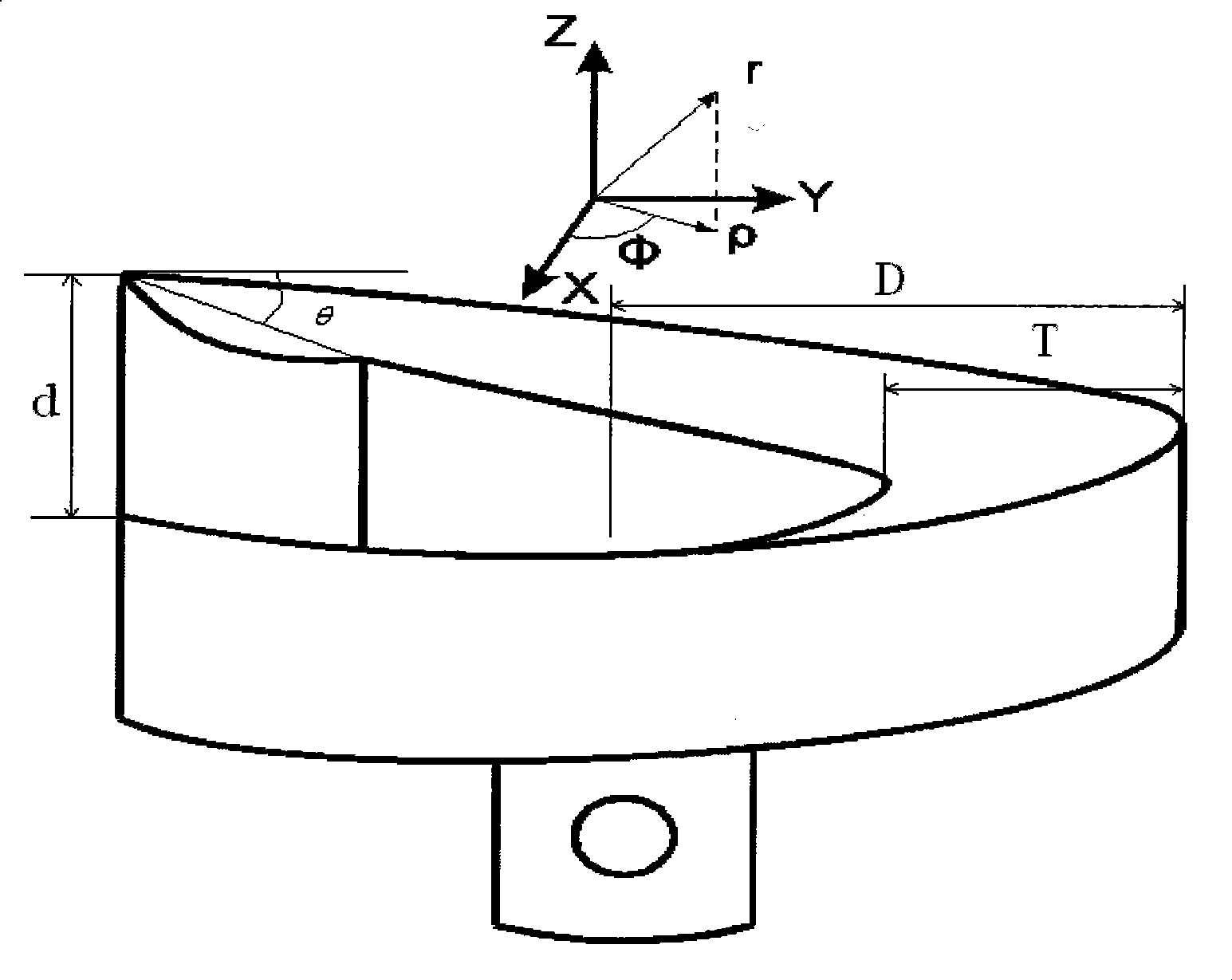
[0019] The first is the design and fabrication of the inclined parabolic generatrix helicoid reflector. The details are as follows:

[0020] According to the principle of differential geometry, the parametric equation of the spiral surface of revolution is written as:

[0021] r → ( ρ , φ ) = ( ρ cos φ , ρ sin φ , d 2 π φ + z 0 ) - - - ( ...


PUM

PropertyMeasurementUnit
Slopeaaaaaaaaaa
Bevel angleaaaaaaaaaa
Widthaaaaaaaaaa

Abstract

The invention discloses a period scanning optical delay line based on the spiral surface reflector of a tilted parabolic type bus. The period scanning optical delay line based on the spiral surface reflector of a tilted parabolic type bus comprises: the spiral surface reflector of the tilted parabolic type bus, a back reflector, and a drive motor. The spiral surface reflector of the tilted parabolic type bus comprises the spiral surface reflector of a convex surface type tilted parabolic type bus and the spiral surface reflector of a concave surface type tilted parabolic type bus; the back reflector is used for controlling light beams to be reflected by the period scanning optical delay line of the spiral surface reflector of the tilted parabolic type bus along the original path. The period scanning optical delay line based on the spiral surface reflector of the tilted parabolic type bus has the advantages that: the spiral surface reflector of the tilted parabolic type bus and the back reflector are combined to enlarge the linear delay time, and eliminate the translation motion of a one-way spiral surface delay line on reflected light to lead the delay line to be simple and compact in structure.

Description

technical field [0001] The invention relates to a periodic scanning optical delay line based on an inclined parabolic generatrix helicoid reflector, and belongs to the technical field of time-resolved optical delay lines. Background technique [0002] In the field of optics and optoelectronics, people have been working hard to develop optical delay lines. The optical delay line is a device that realizes the precise and controllable relative delay time between the coherent light pulses participating in the experiment through technical means. Optical delay line is a key component of time-resolved optical system, and has a wide range of application technologies, such as: THz time-domain spectrum technology, ultra-fast time-resolution spectroscopy technology, time-resolved interferometric spectroscopy technology, optical coherence tomography technology and optical pump Pu-detection technology, etc. [0003] There are various technologies to realize optical delay. The simplest ...

Claims


Application Information

Patent Timeline
IPC IPC(8): G02B26/10G02B26/08G02B5/08G02B5/10
Inventor 邢岐荣王月宾王昌雷刘丰
Owner TIANJIN UNIV
Why Eureka
Try Eureka