OPC correcting method for forming auxiliary through hole

A polygonal and metal wire technology, applied in the field of OPC correction for forming auxiliary vias, can solve the problems of reduced pass rate, danger, open circuit, etc., to reduce the possibility of open circuit, improve the process tolerance, and reduce the number of effects.

Inactive Publication Date: 2009-05-13
SEMICON MFG INT (SHANGHAI) CORP
View PDF0 Cites 5 Cited by
  • Summary
  • Abstract
  • Description
  • Claims
  • Application Information

AI Technical Summary

Problems solved by technology

This approach can be very dangerous when process tolerances are small, such as blind vias due to photoresist fragments or defects falling into vias
Especially for those vias that are relatively isolated, open circuits are often generated, resulting in a decline in the final yield

Method used


Image

  • OPC correcting method for forming auxiliary through hole
  • OPC correcting method for forming auxiliary through hole
  • OPC correcting method for forming auxiliary through hole

Examples


Embodiment 1

[0081] Figure 1A ~ Figure 1G It is a schematic diagram showing the first embodiment of the present invention, taking a logic product of 0.15 μm as an example to explain the process of providing auxiliary via holes.

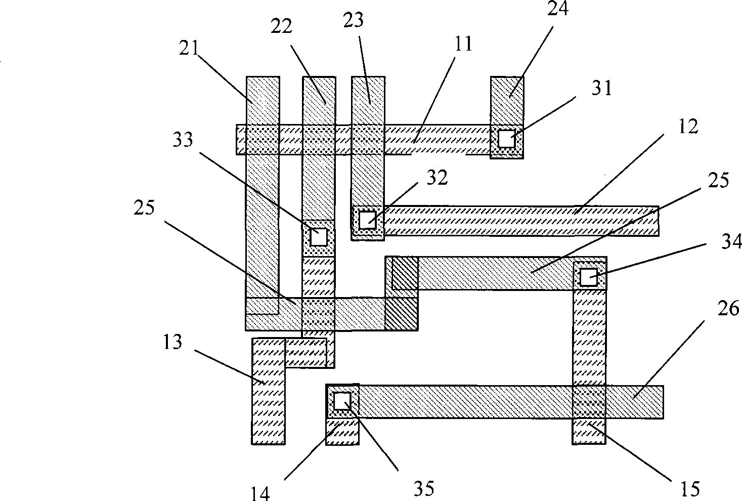
[0082] Such as Figure 1A As shown, there is a first through hole 31 between the first metal line 11 of the first layer and the fourth metal line 24 of the second layer, and there is a hole 31 between the second metal line 12 of the first layer and the third metal line of the second layer. The second through hole 32 has a third through hole 33 between the third metal line of the first layer and the second metal line of the second layer, and has a third through hole 33 between the fifth metal line of the first layer and the fifth metal line of the second layer. The fourth through hole 34 has a through hole 35 between the fourth metal line of the first layer and the sixth metal line of the second layer.

[0083] Such as Figure 1B As shown, first check each via a...

Embodiment 2

[0091] Figure 2A-2H It is a schematic diagram showing the second embodiment of the present invention, taking a logic product of 0.18 μm as an example to explain the formation process of the auxiliary via hole.

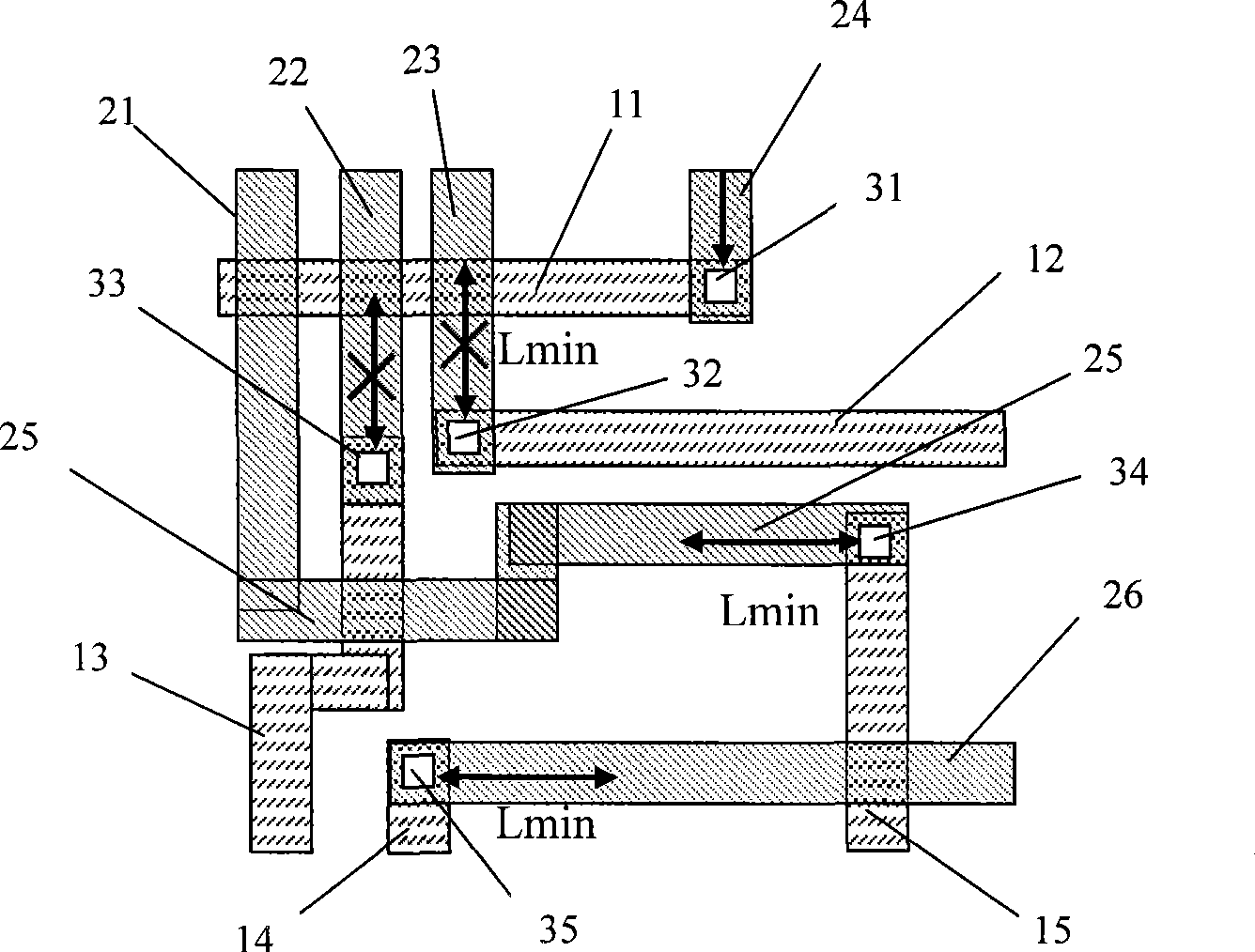
[0092] Such as Figure 2A As shown, there is a first through hole 31 between the first metal line 11 of the first layer and the first metal line of the second layer, and there is a first through hole 31 between the second metal line 12 of the first layer and the second metal line of the second layer. Two through holes 32 , a third through hole 33 , and a fourth through hole 34 .

[0093] Generally, the through hole whose distance with any other surrounding through holes is greater than Lmin is regarded as an isolated through hole. Among the above through holes, the through hole 31 is an isolated through hole, such as Figure 2B shown.

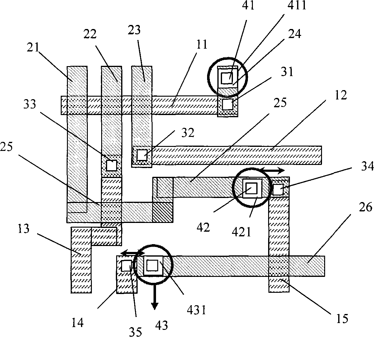
[0094] Such as Figure 2C As shown, four auxiliary through holes are set at the minimum design interval (Min-Design-Pitch) around...


PUM


Abstract

An OPC correction method for forming an auxiliary through hole is as follows: other through holes and metal wires are searched in a certain range nearby isolated through holes between two layers of metal wires; auxiliary through holes are formed nearby the isolated through holes; the through holes and the metal wires are not existed in the certain range of the isolated through holes; the auxiliary through holes extend a size added value towards periphery, and then extend towards the direction of original through holes to be connected with the original through holes and overlap with the under layer metal wire; and finally the conventional OPC correction is carried out on the improved metal wire and the layout of the through holes.

Description

technical field [0001] The invention relates to an OPC (Optical Proximity Correction) correction method for integrated circuit layout on a mask used in semiconductor manufacturing, in particular to an OPC correction method for forming auxiliary through holes for isolated through holes between two layers of metal lines. Background technique [0002] In the back-end manufacturing process of semiconductors, in order to form metal interconnection lines, it is necessary to form via holes between two adjacent layers of metal lines to realize metal interconnection. As circuit density increases and critical dimensions become smaller and smaller, the size of wires and wire spacing and through holes becomes smaller and denser, even reaching sub-micron. When the integrated circuit pattern on the mask is transferred to the photoresist layer on the wafer through exposure, deformation often occurs due to the optical proximity effect, and the through holes of the same size in the pattern s...

Claims


Application Information

Patent Timeline
Patent Type & Authority Applications(China)
IPC IPC(8): G03F1/14G03F1/36
Inventor 洪齐元
Owner SEMICON MFG INT (SHANGHAI) CORP
Why Eureka
Try Eureka