Injecting flow guiding silt-proof method

A technology of anti-silting and spraying pipes, which is applied in sea area engineering, water conservancy engineering, climate change adaptation, etc., can solve problems that affect the normal berthing of ships, easy sedimentation, endangering the safety of ships, etc., and achieve the protection of ecological environment and natural landscape , The diversion beam effect is good, and the stability is guaranteed

Inactive Publication Date: 2009-05-20
大融合(广东)海洋休闲渔业发展有限公司
View PDF0 Cites 14 Cited by
  • Summary
  • Abstract
  • Description
  • Claims
  • Application Information

AI Technical Summary

Problems solved by technology

[0007] 2. The depth of the harbor basin where the ship is docked generally meets the requirements of use after manual excavation. Due to the water depth and relatively small flow velocity in this area, the sediment is particularly easy to settle here, resulting in sedimentation in the ha...

Method used


Image

  • Injecting flow guiding silt-proof method
  • Injecting flow guiding silt-proof method
  • Injecting flow guiding silt-proof method

Examples


Embodiment 1

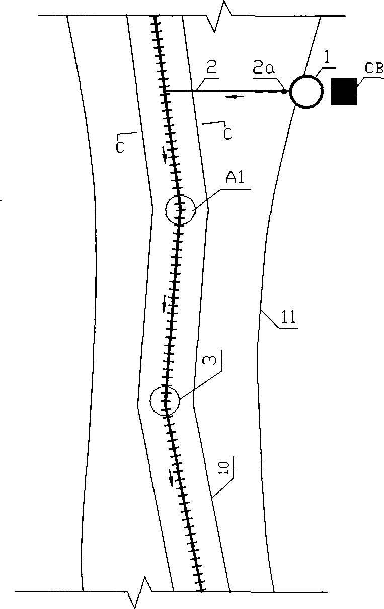
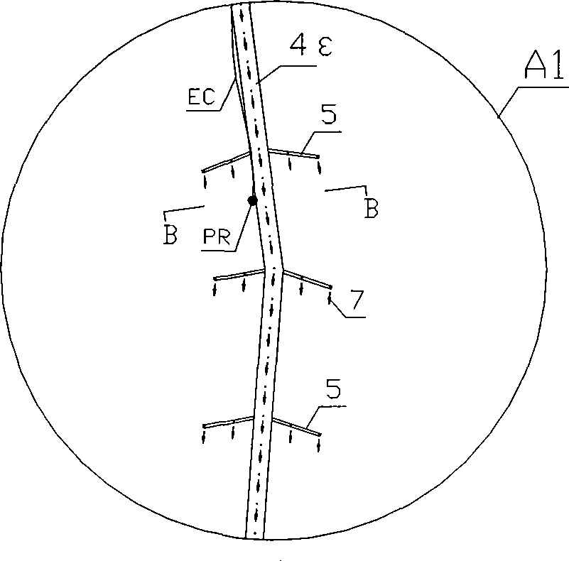
[0036] One or more main pipes are laid on the bottom surface of the main waterway, and spray holes are opened at a certain distance on the upper or lower part or side of the main pipes, and a water column with a certain pressure is injected through the spray holes; pressure measuring devices are installed along the main pipes.

[0037] see Figure 1~4

[0038] 1. Build a water supply facility 1 upstream of the waterway; the water volume of the water supply facility 1 should be able to ensure the continuous supply of water with a certain pressure to the branch pipe network 3 and keep the pressure stable.

[0039] The water supply facilities may be reservoirs, pools, deep wells, water diversion pipes, transmission and distribution networks, pumping stations, public water supply stations and other facilities that can provide a large amount of water.

[0040] 2. Build a monitoring center CB near the water supply facilities to monitor and maintain the normal operation of the jet d...

Embodiment 2

[0048] The pipe network is laid on the bottom surface of the deep water area, and the upper or lower part of the pipe network or the side is provided with injection holes at a certain distance, and a water column with a certain pressure is injected through the injection holes.

[0049] see Figure 5-12

[0050] 1. Build a water supply facility 18 near the harbor basin; the water output of the water supply facility 18 should be able to ensure the continuous supply of water with a certain pressure to the injection pipe network and keep the pressure stable.

[0051] 2. Build a monitoring center CB near the water supply facilities to monitor and maintain the normal operation of the jet diversion system.

[0052] 3. Excavate the harbor basin according to the designed harbor basin location and water depth.

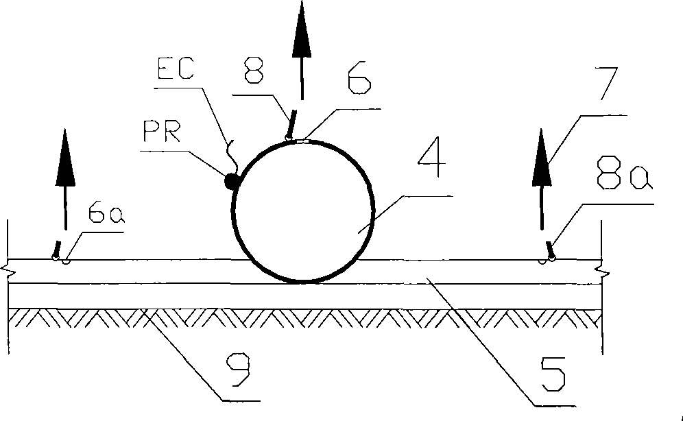
[0053] 4. Lay the injection pipe network on the bottom surface 21 of the harbor basin. The injection network includes a main pipe 14 and a discharge pipe 16 arranged in parall...


PUM


Abstract

The invention relates to a method for preventing silt by injection and diversion, including laying injection pipe network underwater which communicates with water supply facilities. The injection pipe network comprises at least one main pipe which is provided with injection holes with an interval, and water column having certain pressure can be ejaculated through the injection holes. The injection pipe network also comprises a total pipe and a discharge pipe arranged parallel with the total pipe, the total pipe communicates with water supply facilities, and the total pipe is communicated with the parallel discharge pipe through a plurality of branch pipes; the total pipe and the branch pipes are all provided with injection holes, and water column having certain pressure can be ejaculated through the injection holes. The method of the invention is applied to the water areas where water can flow naturally such as rivers and estuary, and can prevent the main water channel from being silted by silt and keep the direction of the main water channel not changing; can be applied to deep water regions excavated by manpower to prevent silt from depositing in the region, can move the silt from the pipe network under the function of water flow to achieve the effect of silt prevention; and is suitable for the harbor basin of harbor.

Description

technical field [0001] The invention relates to a jet diversion anti-silting method, which is applied to water areas where water flows naturally, such as rivers, rivers, and sea estuaries, so that the mainstream waterway will not be silted up by sediment and the direction of the mainstream waterway will not change; it can be monitored in real time The water depth along the line can help you understand the state of the waterway. It is most suitable for the drainage of navigable waterways or open rivers where ships pass. Applied in artificially excavated deep water areas, it can prevent sediment from settling in this area, and make the sediment move away from the pipe network area under the action of water flow to achieve the effect of anti-silting; it is most suitable for harbor basins of port terminals. Background technique [0002] More than 90% of the world's material flow is realized by water transport by ships. It can be seen how important water transport is to the nati...

Claims


Application Information

Patent Timeline
IPC IPC(8): E02B3/02
CPCE02F5/28E02B3/023E02F3/9206Y02A10/00
Inventor 卢如年
Owner 大融合(广东)海洋休闲渔业发展有限公司
Why Eureka
Try Eureka