
Core voltage control device

A core voltage and control device technology, applied in the field of core voltage control devices, can solve problems such as circuit malfunctions and power consumption, and achieve the effects of avoiding malfunctions and reducing power consumption

Inactive Publication Date: 2009-05-20
吴娅峤
View PDF0 Cites 6 Cited by
  • Summary
  • Abstract
  • Description
  • Claims
  • Application Information

AI Technical Summary

Problems solved by technology

However, if the core voltage of the central processing unit is not stopped immediately when the computer system (or server) is shut down, causing additional power consumption, and some circuits continue to operate, which may also cause circuit malfunctions

Method used


Image

  • Core voltage control device

Examples


Embodiment Construction

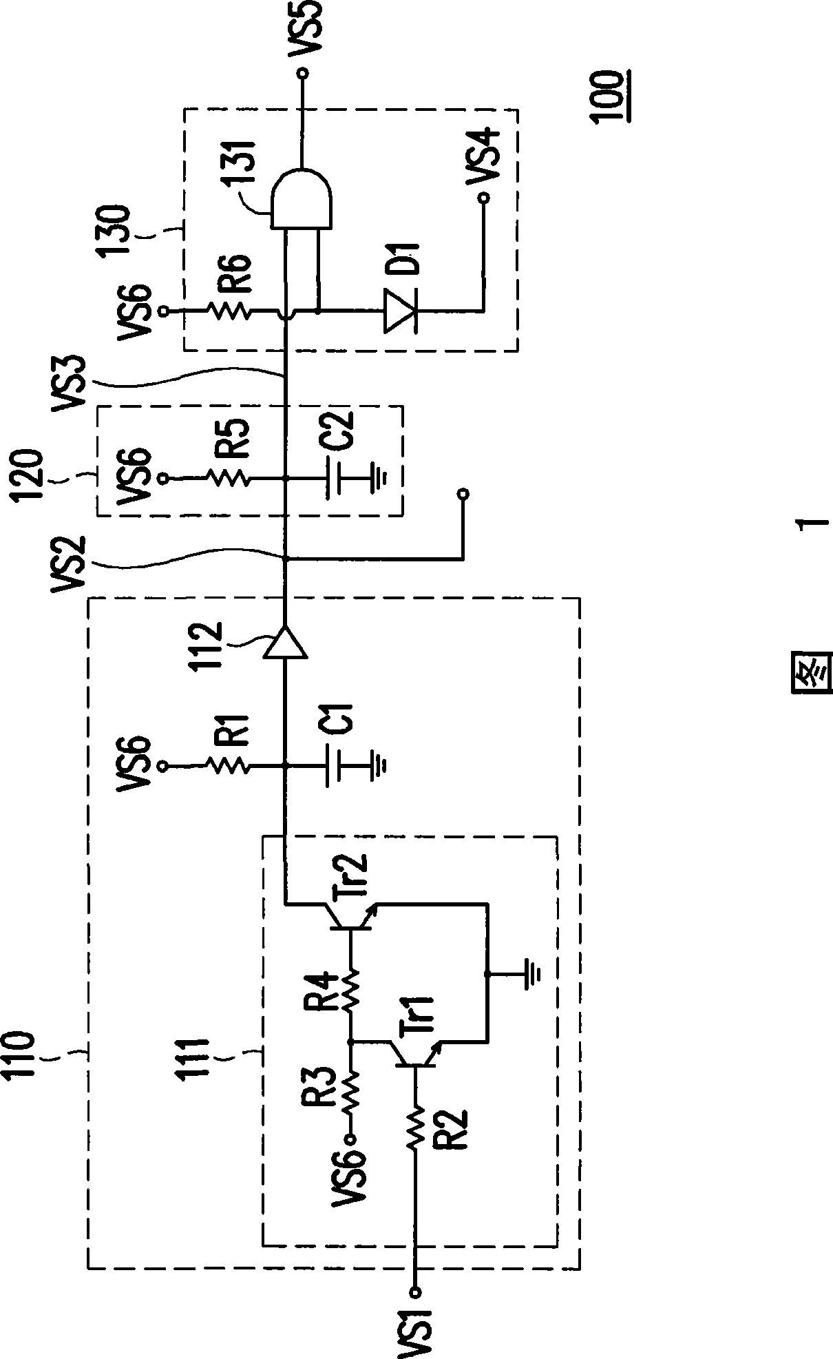
[0013] FIG. 1 is a circuit diagram of a core voltage control device according to an embodiment of the present invention. The core voltage control device 100 of this embodiment is suitable for a central processing unit (not shown). Please refer to FIG. 1 , the core voltage control device 100 includes a level conversion unit 110 , a delay unit 120 and a logic unit 130 . The input terminal of the level conversion unit 110 receives the first voltage signal VS1, and performs level conversion on the first voltage signal VS1, and generates a second voltage signal VS2 at the output terminal of the delay circuit 110, wherein the first voltage signal VS1 is used for Indicates the power-on stable state, and the second voltage signal VS2 is used to indicate the magnitude of the core voltage.

[0014] The delay unit 120 is used for delaying the second voltage signal VS2 to generate a third voltage signal VS3. The logic unit 130 is coupled to the delay unit 120, and is used for logical op...


PUM


Abstract

The invention discloses a core voltage control device, which is suitable for a central processing unit. The core voltage control device comprises a level conversion unit, a time delay unit and a logical unit, wherein the input end of the level conversion unit receives a first voltage signal and is used for level conversion of the first voltage signal, and the output end of the level conversion unit generates a second voltage signal, wherein the first voltage signal indicates the stable electrifying state, and the second voltage signal indicates the size of the core voltage; the time delay unit performs time delay the second voltage signal, so as to generate a third voltage signal; and the logical unit is coupled to the time delay unit, and used for performing logic operation on the third voltage signal and a fourth voltage signal which is transmitted by a power supply and generating a fifth voltage signal to control whether a core voltage generator supplies the core voltage to the central processing unit or not, wherein the fourth voltage signal indicates the power state.

Description

technical field [0001] The present invention relates to a voltage control device, and in particular to a core voltage control device for a central processing unit. Background technique [0002] After the computer system (or server) is turned on, the components in the computer system (or server) will not be powered on at the same time, but will provide the voltage required by each component according to the general power-on procedure. , wherein the core voltage of a central processing unit (CPU) is provided at the latest. The above-mentioned power-on procedure is as follows in sequence: first, the computer system (or server) is powered on. Then, after the voltages required by each component are powered on and stabilized, a power-on stable state signal is generated. Afterwards, the power-on steady-state signal is delayed to generate an enable signal for the core voltage of the CPU. When the core voltage generator receives the enable signal, it generates the core voltage to ...

Claims


Application Information

Patent Timeline
Patent Type & Authority Applications(China)
IPC IPC(8): G06F1/26G06F1/32
Inventor 黄岚刘士豪
Owner 吴娅峤
Learn More