

Hydraulic control system for working machine
A technology for hydraulic control systems and working machines, which can be applied to fluid pressure actuation system components, mechanical equipment, earth movers/shovels, etc., and can solve problems such as wasted energy loss
- Summary
- Abstract
- Description
- Claims
- Application Information
AI Technical Summary
Problems solved by technology
Method used
Image

Examples
Embodiment Construction
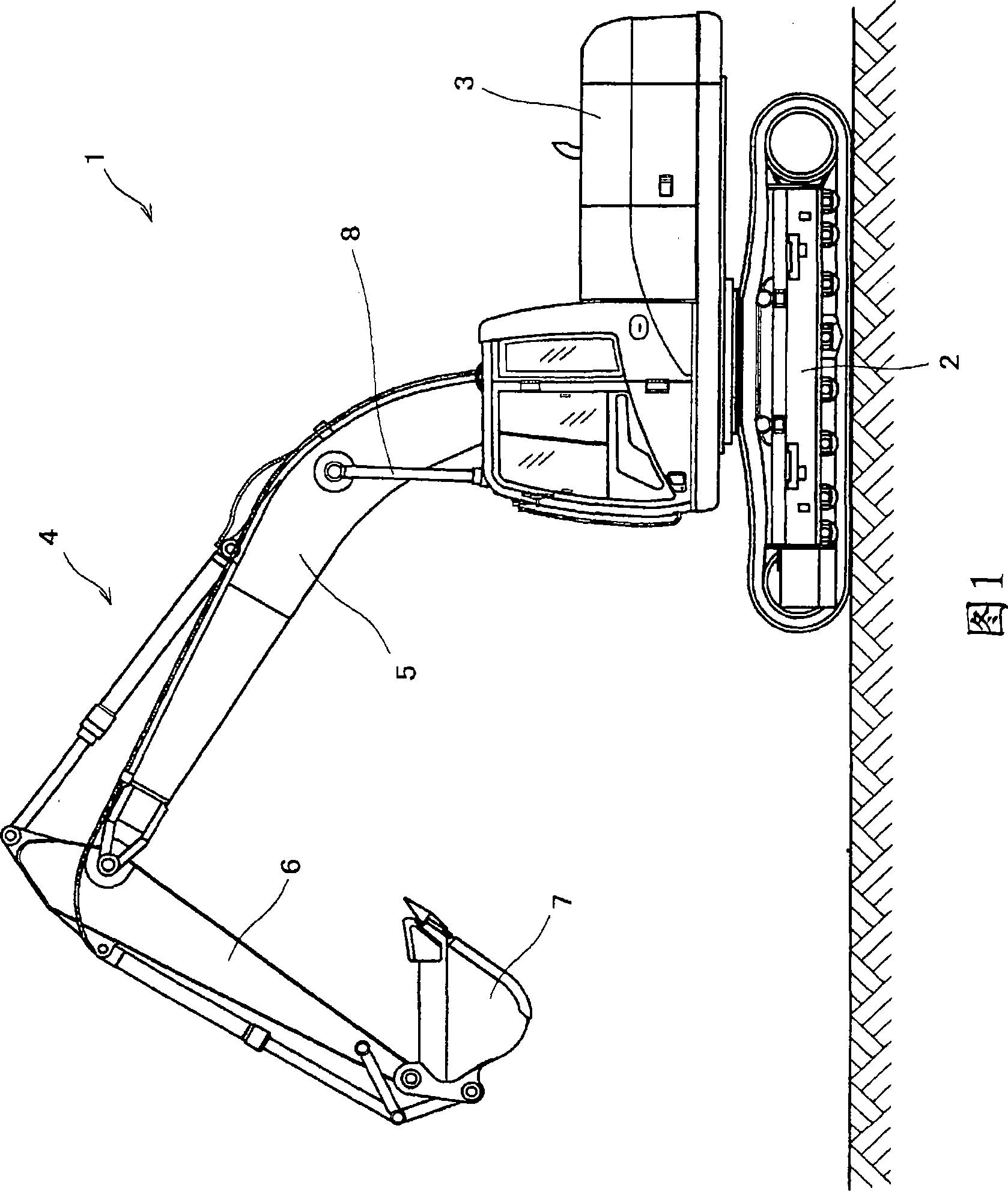
[0007] Embodiments of the present invention will be described below with reference to the drawings. In FIG. 1, reference numeral 1 is a hydraulic excavator as an example of a working machine. This hydraulic excavator 1 includes a crawler-type undercarriage 2, an upper swing body 3 rotatably supported above the undercarriage 2, and In parts such as the working part 4 in front of the upper turning body 3, the working part 4 further includes a boom (boom) 5 supported on the upper turning body 3 at a base end portion that is freely swingable up and down, and is supported on the front and rear swinging body freely. An arm (arm) 6 at the front end of the boom 5 , a bucket 7 attached to the front end of the arm 6 , and the like.
[0008] Reference numeral 8 is a pair of left and right boom cylinders (corresponding to hydraulic cylinders in the technical solution of the present invention) that perform telescopic motions to swing the above-mentioned boom 5 up and down. 8a (equivalent ...
PUM
 Abstract
Description
Claims
Application Information