Clamping mechanism for chucking appliance system

A technology of clamping device and fixture system, applied in the direction of positioning device, clamping, manufacturing tools, etc., can solve the problems of noise pollution, energy consumption, large energy loss, etc., and achieve effective control of output displacement, high energy utilization rate, and structural simple effect

Inactive Publication Date: 2009-05-27
SUZHOU UNIV
View PDF2 Cites 11 Cited by
  • Summary
  • Abstract
  • Description
  • Claims
  • Application Information

AI Technical Summary

Problems solved by technology

①The mechanical energy required by the clamping force has to go through many energy form conversion links, resulting in large energy loss and low energy utilization
②There is a high-speed rotating mechanical transmission device, and the noise pollution is relatively serious
③Hydraulic transmission fixtures cannot avoid oil leakage in many links, and thus cause serious ground and air pollution
④Many hydraulic transmission fixtures consume energy in order to maintain continuous clamping force during the cutting process, which is a waste of energy

Method used


Image

  • Clamping mechanism for chucking appliance system
  • Clamping mechanism for chucking appliance system
  • Clamping mechanism for chucking appliance system

Examples


Embodiment 1

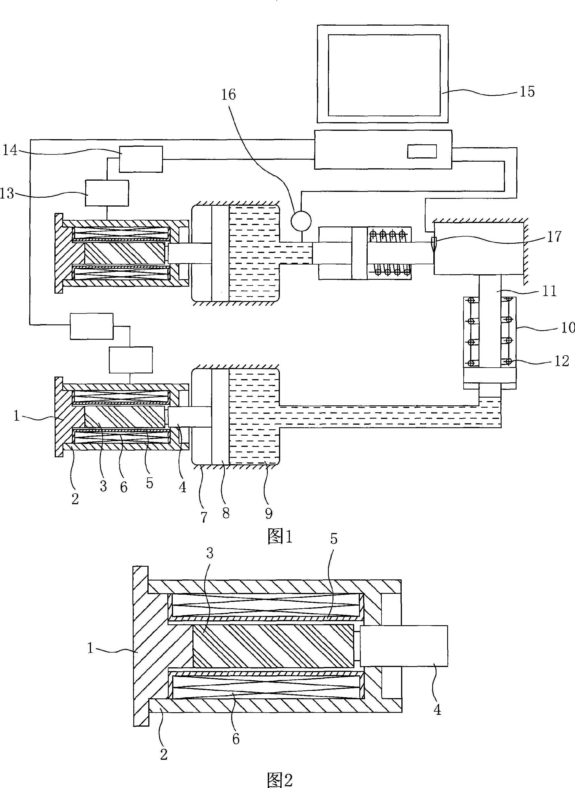
[0035]Embodiment 1: Referring to accompanying drawings 1 to 2, a clamping device for a fixture system includes a micro-displacement driving device, a stroke amplification device and a displacement output device, and the micro-displacement driving device includes a base 1 , the base is provided with a jacket 2 outside, and a giant magnetostrictive rod 3 is arranged inside it. One end of the giant magnetostrictive rod is fixedly connected with the base, and the other end is connected with an output rod 4. The two ends of the giant magnetostrictive rod A skeleton 5 is arranged on the side, and a coil 6 is arranged between the skeleton and the outer jacket; the stroke amplification device includes a piston cylinder 7 with a piston 8 inside, and one end of the piston is connected to the output rod of the micro-displacement drive device. It is fixedly connected, and a hydraulic chamber is formed between the other end and the piston cylinder, and a hydraulic medium 9 is arranged insid...


PUM


Abstract

The invention discloses a clamping device used for a clamp system, comprising a micro-displacement driving device, a stroke magnification device and a displacement output device. The clamping device is characterized in that the micro-displacement driving device comprises a base; a sleeve is arranged outside the base and a super magnetostrictive rod is arranged inside the base; one end of the super magnetostrictive rod is fixedly connected with the base and the other end thereof is connected with an output ring; two sides of the super magnetostrictive rod are provided with frameworks; a coil is arranged between the framework and the sleeve; the stroke magnification device comprises a piston cylinder which is internally provided with a piston; one end of the piston is fixedly connected with the output rod and the other end thereof is provided with a hydraulic chamber which is filled with liquid medium; the displacement output device comprises an output cylinder which is internally provided with an output piston rod, one end of which is fixedly connected with the hydraulic chamber of the stroke magnification device. In the invention, the micro-displacement driving device and stroke magnification device are adopted to drive the displacement output device to carry out the clamping, thus improving the utilization efficiency of the energy resource, and having good stability and generating no pollution.

Description

technical field [0001] The invention relates to a clamping device, in particular to a clamping device driven by a giant magnetostrictive material and a stroke amplification device. Background technique [0002] Whether it is traditional machinery manufacturing or modern machinery manufacturing, the role of machine tool fixtures is very important. The core of the machine tool fixture is the clamping device. [0003] At present, most of the motorized clamping devices widely used in production adopt pneumatic or hydraulic transmission, and cooperate with appropriate clamping mechanisms. The main reason why people use a large number of fluid transmission clamps is that one can obtain a much larger clamping force than manual clamps, and the other is to facilitate the automatic control of the positioning and clamping process. Chinese utility model patent CN2855645Y discloses a pneumatic clamping device, which is mainly composed of a cylinder, a body, a slider, a connecting rod, ...

Claims


Application Information

Patent Timeline
Patent Type & Authority Applications(China)
IPC IPC(8): B23Q3/06
Inventor 王明娣钟康民左敦稳王珉
Owner SUZHOU UNIV
Why Eureka
Try Eureka