Digital decimation filter

A decimation filter and filter technology, applied in the filter field, can solve the problems of large passband drop, complex tap coefficients, and insufficient half-band filter attenuation, etc., to achieve large passband drop, low noise power, and low power consumption. small effect

Active Publication Date: 2009-05-27
SHENZHEN TCL IND RES INST
View PDF0 Cites 5 Cited by
  • Summary
  • Abstract
  • Description
  • Claims
  • Application Information

AI Technical Summary

Problems solved by technology

[0011] The purpose of the present invention is to provide a digital decimation filter, which aims to solve the problem that the attenuation of the half-band filter of the existing digital decimation filter is not large enough in the aliasing band, the tap coefficients are complex, and the existing digital decimation filter The problem of large passband drop caused by

Method used


Image

  • Digital decimation filter
  • Digital decimation filter
  • Digital decimation filter

Examples


Embodiment Construction

[0028] In order to make the object, technical solution and advantages of the present invention clearer, the present invention will be further described in detail below in conjunction with the accompanying drawings and embodiments.

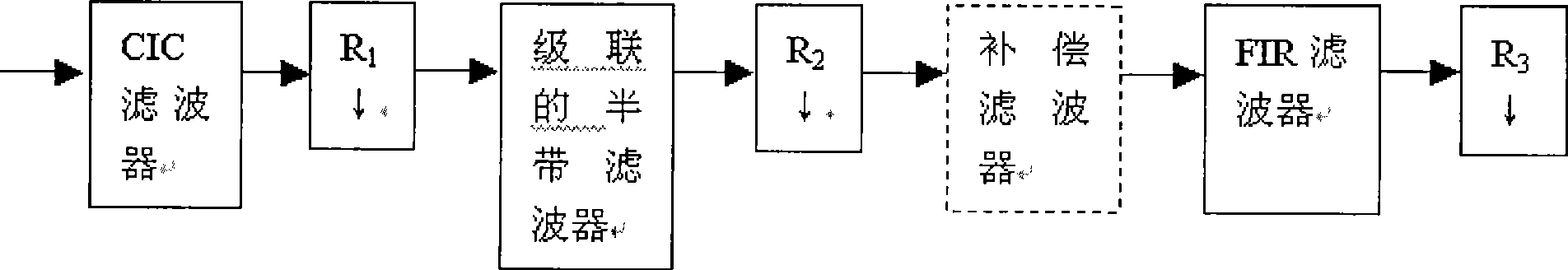
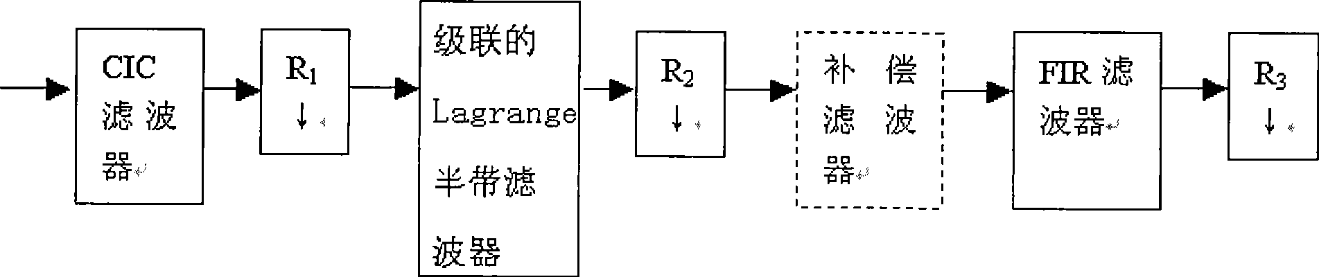
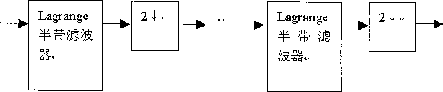
[0029] see figure 2 , is a schematic structural diagram of the digital decimation filter of the present invention. The digital decimation filter of the present invention includes: cascaded integral comb (CIC) filter, cascaded Lagrange half-band filter and FIR filter. The cascaded integral comb filter, the cascaded Lagrange half-band filter and the FIR filter are connected in sequence.

[0030] For FIR filter, F(z)=z N-1 (1+z -1 ) N R(z), where R(z) is a polynomial of degree N-2 (N is an even number). F(z) can generate a half-band filter, and by choosing R(z) appropriately, the frequency response of filter F(z) F(e jω) is maximally flat at ω=0 and ω=π. This type of half-band filter is called a binomial or maxflat filter. The maximum flatnes...


PUM


Abstract

The invention provides a digital decimation filter. The digital decimation filter comprises a cascade integral comb filter, a cascaded Lagrange half-band filter and an FIR filter, which are orderly connected. The digital decimation filter has the advantages of less pass band dropping, small quantized noise power after filtering, and less power consumption.

Description

technical field [0001] The present invention relates to filters, in particular to a digital decimation filter. Background technique [0002] A digital decimation filter (Digital Decimation Filter) is applied in an analog-to-digital converter (ADC) based on Σ-Δ modulation. Analog-to-digital converters based on sigma-delta modulation use oversampling, noise shaping, and digital decimation filters to achieve higher signal-to-noise ratios. Oversampling is used because: As the multiple R increases, the quantization noise spectrum overlaps with the signal spectrum less and less. Noise shaping concentrates the noise energy to high frequencies. The digital decimation filter eliminates quantization noise within the frequency band π / R<|ω|≤π without changing the signal components, thus improving the signal-to-noise ratio. Digital decimation filters can be used not only in ADCs based on Σ-Δ modulation, but also in digital down converters (DDC) and digital up converters (DUC). [...

Claims


Application Information

Patent Timeline
Patent Type & Authority Applications(China)
IPC IPC(8): H03H17/02
Inventor 周化雨
Owner SHENZHEN TCL IND RES INST
Why Eureka
Try Eureka