Tool head, machine tool and boring method of bore of cylinder block using the machine tool

A technology of a machine tool and a cutter head, which is applied in the field of cutter head, machine tool and boring cylinders using the machine tool, can solve the problem that the rough grinding head 502 and the fine grinding head 504 cannot be rapidly expanded and cannot have too many changes. and other problems, to achieve the effect of simple structure and improved productivity

Inactive Publication Date: 2009-05-27
HONDA MOTOR CO LTD
View PDF5 Cites 16 Cited by
  • Summary
  • Abstract
  • Description
  • Claims
  • Application Information

AI Technical Summary

Problems solved by technology

[0027] However, with regard to the latter process, it has been confirmed that even if the force used to lift the rough grinding cone 510 and the fine grinding cone 512 increases, the force used to expand the rough grinding head 502 and the fine grinding head 504 can only be slowly increased. change, or in practice there cannot be too much variation, i.e., the coarse grinding head 502 and the fine grinding head 504 cannot expand rapidly
[0028] The above problem is caused by the workpiece being drawn along the rough grinding cone 510 Figure 38 The direction indicated by the arrow A1 in is lifted to radially expand the coarse grinding head 502 in the direction indicated by the arrow B. of

Method used


Image

  • Tool head, machine tool and boring method of bore of cylinder block using the machine tool
  • Tool head, machine tool and boring method of bore of cylinder block using the machine tool
  • Tool head, machine tool and boring method of bore of cylinder block using the machine tool

Examples


Embodiment Construction

[0088] A machine tool according to an embodiment of the present invention will be described below with reference to the drawings.

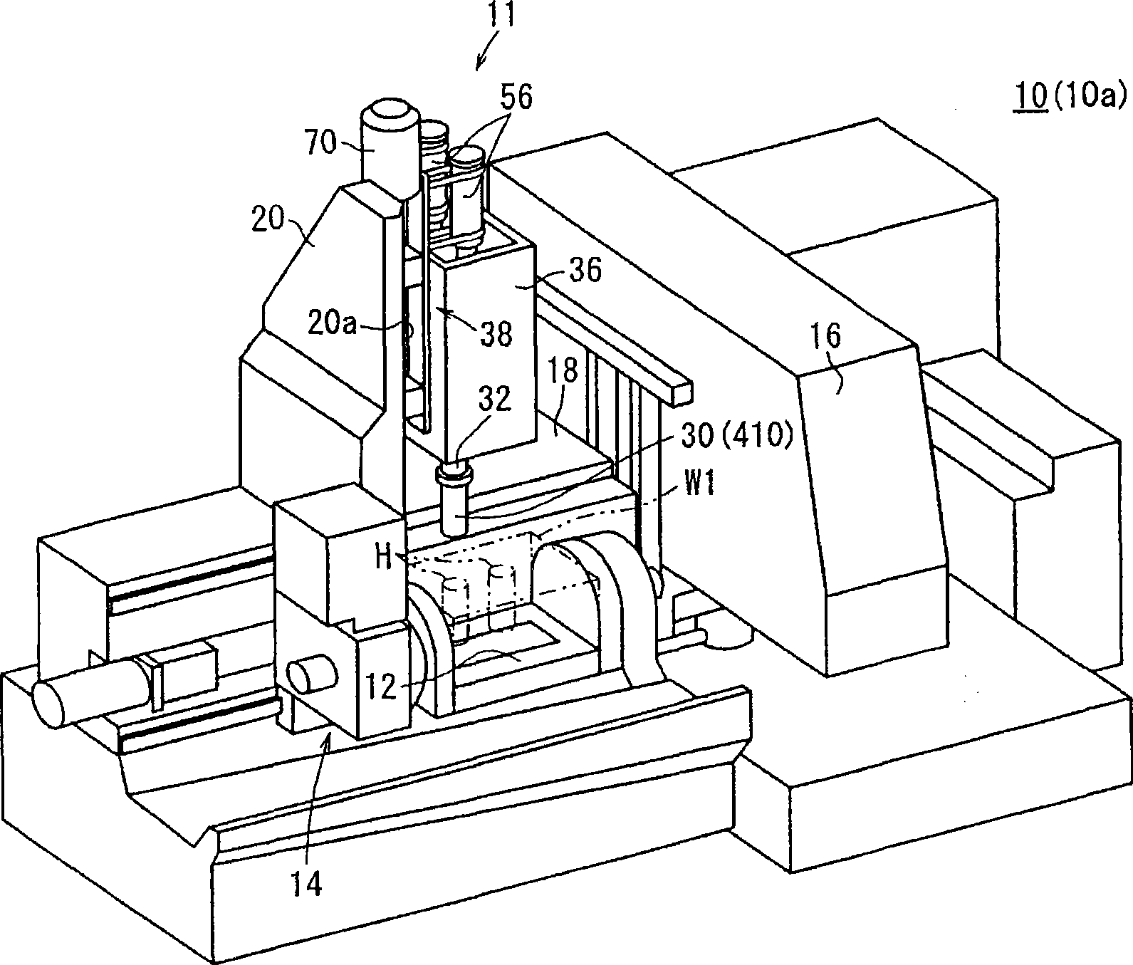
[0089] as in figure 1 As shown in , the combined machine tool 10 according to the first embodiment of the present invention is arranged in a production line for machining a cylinder, for example, a cylinder of an internal combustion engine of an automobile forming a workpiece W1. The machine tool 10 has a spindle actuator assembly 11 for actually boring and honing (grinding) a workpiece W1, a workpiece loader in front of the machine tool, and a pallet 12 for conveying a workpiece on which the workpiece is placed and fixedly mounted. A workpiece conveying mechanism 14 reciprocally movable between the lower portion of the spindle actuator assembly 11 , and a monitoring console 16 for electronically controlling the spindle actuator assembly 11 and the workpiece conveying mechanism 14 . The machine tool 10 is arranged as a system in a production lin...


PUM


Abstract

The invention relates to a tool head, a machine tool and a boring method for boring a cylinder b6lock using the machine tool. A spindle drive unit (11) of the machine tool (10) drives the spindle (32). The tip end of the spindle (32) is provided with a boring tool (100) and a tool head (30) having a rough grinding stone (102) and a finishing grinding stone (104). The spindle drive unit (11) has a first support unit (34) and a second support unit (36) capable of receiving the spindle (32) therethrough and supporting it rotatably, a linear motor (58) and a column slide mechanism (38) for moving the first and second support unit (34, 36) in the axis direction of the spindle (32), and a spindle motor (44) for rotating the spindle (32).

Description

technical field [0001] The invention relates to a tool head with a grinding tool, a machine tool with a boring tool and a grinding tool, and a method of boring a cylinder using such a machine tool. Background technique [0002] Machining treatment for boring a cylinder block constituting an engine component includes: boring treatment (finish boring treatment, etc.) for forming a hole in the cylinder body to a predetermined diameter; and grinding for subsequent grinding of the surface of the hole Processing (honing processing, etc.). If the boring and grinding operations can be performed consecutively on a single spindle of the machine tool, the cylinder will not create misalignment with respect to the tool that would otherwise result if the cylinder were moved between different machines and re-clamped. Misalignment of the body with respect to the tool. Therefore, the cylinder block can be processed properly and efficiently. To continuously perform the boring process and t...

Claims


Application Information

Patent Timeline
Patent Type & Authority Applications(China)
IPC IPC(8): B23B41/00B23B39/00B23P23/02B24B33/08
Inventor 定冈秀树大岛拓洋野上真二铃木稔大内诚菊池正德
Owner HONDA MOTOR CO LTD
Why Eureka
Try Eureka