Electron beam recording apparatus

一种记录装置、电子束的技术,应用在电子束载流子记录、光学记录、数据记录等方向,能够解决妨碍焦点精确校正、磁场的变化不是很有效、不能精确地校正焦点等问题

Inactive Publication Date: 2009-05-27
RICOH KK +1
View PDF5 Cites 7 Cited by
  • Summary
  • Abstract
  • Description
  • Claims
  • Application Information

AI Technical Summary

Problems solved by technology

The generated magnetic field affects the electron beam, which prevents precise correction of the focus and leads to a reduction in exposure quality
[0022] Referring to the electron beam irradiation apparatus of Patent Document 3, according to the method of correcting the displacement of the focus of the electron beam on the master disk due to the change of the magnetic field and adjusting the focus of the electron beam with respect to the target object, the irradiation point of the electron beam is estimated due to a plurality of magnetic detectors The magnetic field nearby, so it is not possible to accurately calculate the disturbing magnetic field in the injecting part of the electron beam
Therefore, the electron beam irradiating apparatus in Patent Document 3 cannot accurately correct the focus, and thus the exposure quality is degraded
[0023] In addition, according to Patent Document 3, due to the equipment configuration, in order to eliminate the influence of the earth's magnetic force, the entire electron beam irradiation equipment must be magnetically shielded
However, due to many limitations in usability and construction, such as ventilation and air-conditioning facilities, this configuration is not very effective against changes in the magnetic field generated inside the shielded equipment
Also, since the whole equipment is magnetically shielded, the electron beam irradiation equipment is large and expensive

Method used


Image

  • Electron beam recording apparatus
  • Electron beam recording apparatus
  • Electron beam recording apparatus

Examples


Embodiment Construction

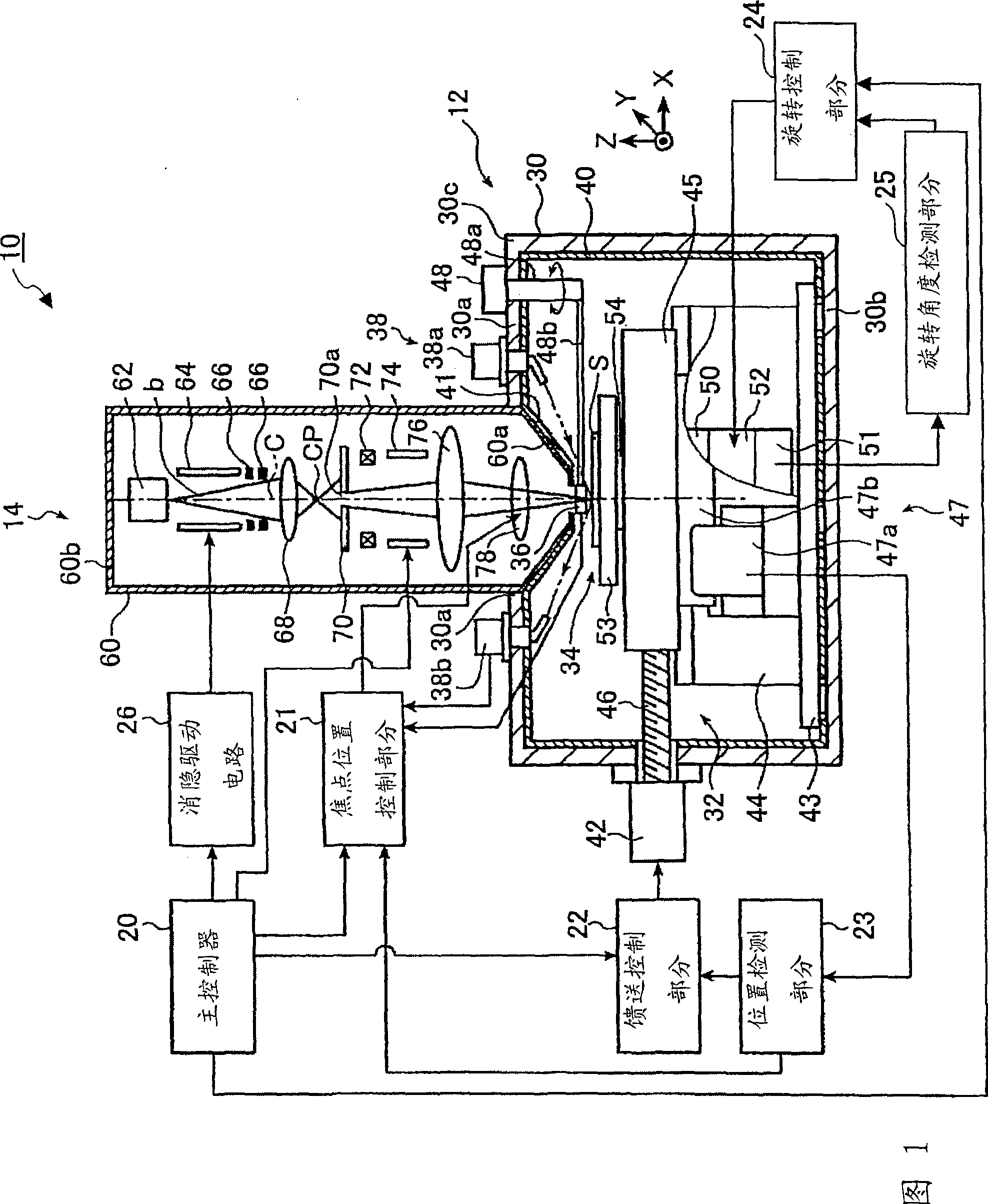
[0048] In the following, an electron beam recording apparatus according to the present invention is described with reference to the drawings. FIG. 1 is a schematic diagram showing an electron beam recording apparatus 10 according to a first embodiment of the present invention.

[0049] The electron beam recording apparatus 10 is used, for example, to produce a master optical disc by printing a pattern on a glass substrate.

[0050] Electron beam recording apparatus 10 includes printing section 12 , electron beam generator 14 , main controller 20 , focus position control section 21 , feed control section 22 , position detection section 23 , rotation control section 24 and rotation angle detection section 25 .

[0051] The main controller 20 is connected to a focus position control section (convergence position control section) 21, a feed control section 22, and a rotation control section 24, and controls the focus position control section (convergence position control section) ...


PUM

PropertyMeasurementUnit
Sensitivityaaaaaaaaaa

Abstract

An electron beam recording apparatus is disclosed that records information onto the surface of a sample by using an electron beam. The electron beam recording apparatus includes an electron source that irradiates the electron beam, a magnetic detector that is configured to move onto and out of an irradiation axis and acquires magnetic information on the irradiation axis, a convergence position control part that calculates a convergence position correction amount for correcting a convergence position of the electron beam with respect to the surface of the sample based on the magnetic information, and a convergence position adjusting part that adjusts the convergence position of the electron beam with respect to the surface of the sample. The convergence position control part causes the convergence position adjusting part to adjust the convergence position of the electron beam with respect to the surface of the sample based on the convergence position correction amount.

Description

technical field [0001] The present invention relates to an electron beam recording apparatus for recording information by irradiating an electron beam to a predetermined position, and more particularly to an electron beam recording apparatus for producing a master of optical disk by using an electron beam printing pattern . Background technique [0002] In recent years, there has been an increasing demand for precision improvements in microfabrication techniques such as mastering optical disc exposure techniques and semiconductor techniques. For example, optical discs are produced by a master disc production process for producing a stamper from a glass plate, and a magnetic disk production process for producing an optical disc with an injection mold on which a stamper is mounted. [0003] In a typical master production process, the master production machine emits visible light, ultraviolet laser, etc. from a light source in the surrounding environment, and focuses the light...

Claims


Application Information

Patent Timeline
Patent Type & Authority Applications(China)
IPC IPC(8): G11B7/26G11B9/10G11B11/03
CPCG11B9/10G11B11/03G11B7/261G11B7/26H01J37/147H01J37/21H01J37/30
Inventor 小原隆宫崎武司
Owner RICOH KK
Why Eureka
Try Eureka