
Gas piping structure of PECVD device

A gas pipeline and gas technology, applied in gaseous chemical plating, metal material coating process, coating and other directions, can solve problems affecting the process, etc., to prevent the accumulation of particles in the pipeline, and ensure the stability and safety of the process.

Inactive Publication Date: 2009-06-03
SHANGHAI HUA HONG NEC ELECTRONICS
View PDF0 Cites 2 Cited by
  • Summary
  • Abstract
  • Description
  • Claims
  • Application Information

AI Technical Summary

Problems solved by technology

Under normal circumstances, the above design structure is safe, but when SiH 4 , O 2 and NH 3 When the pneumatic valve leaks, the reducing SiH 4 , NH 3 Will and O 2 The reaction produces SiO, SiON and other particles accumulate in the pipe, affecting the process
or when SiH 4 The above phenomenon will also occur when the air is not fully purged

Method used


Image

  • Gas piping structure of PECVD device
  • Gas piping structure of PECVD device

Examples


Embodiment Construction

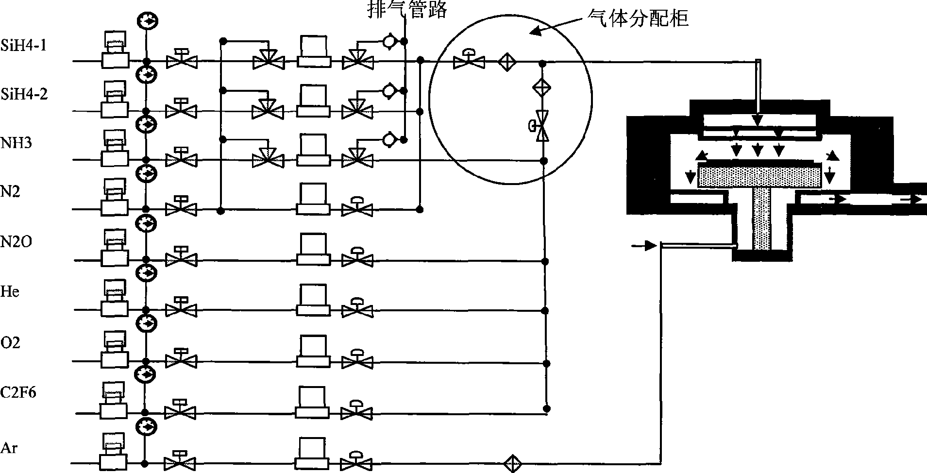
[0009] Such as figure 2 Shown is the gas pipeline structure of the PECVD device of the present invention. In the present invention, all the gas supplied by the upper cavity in the gas pipeline of the existing PECVD device is mixed in the gas distribution cabinet into two-way gas according to the nature of the gas. Access to the mixing structure inside the gas distribution cabinet.

[0010] In the gas pipeline structure of the PECVD device of the present invention, the gas supplied by multiple chambers is fed into the gas distribution cabinet for mixing, and then passed into the rear reaction chamber through the same pipeline; wherein the gas supplied by multiple chambers is divided into reducing gas There are two parts of reducing gas and oxidizing gas, and the reducing gas and oxidizing gas are respectively passed into the gas distribution cabinet through two pipelines for mixing. Reducing gases include: SiH 4 and N 2 , oxidizing gases include: NH 3 , N 2 O, C 2 f 6 ,...


PUM


Abstract

The invention discloses a gas piping structure of a PECVD device; after being added into a gas distribution cabinet to be mixed, the gases supplied by multipath upper chambers are added to a rear reaction chamber through the same pipeline; the gases supplied by multipath upper chambers are divided into reducing gases and oxidizing gases; and the reducing gases and oxidizing gases are respectively added to the gas distribution cabinet to be mixed by two pipelines. Because the invention adds the strong reducing gases and strong oxidizing gases in different pipelines, the particle packing of pipelines can be effectively avoided, which ensures the safety and stability of techniques.

Description

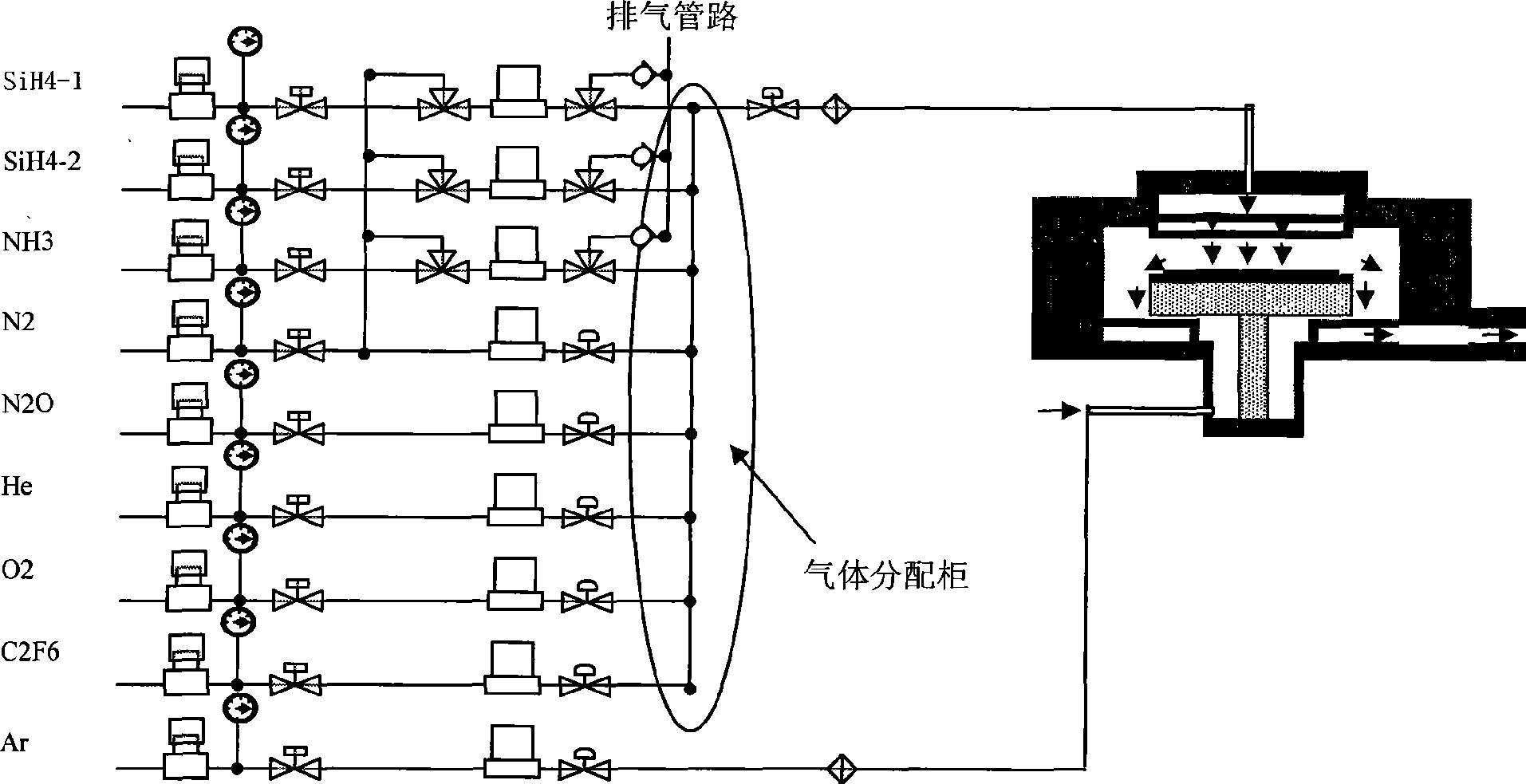
technical field [0001] The invention relates to a gas pipeline structure of a PECVD (Plasma Chemical Vapor Deposition) device. Background technique [0002] Such as figure 1 As shown, it is the gas pipeline structure of the existing PECVD device, and the upper chamber supply gas includes SiH 4 -1, SiH 4 -2, NH 3 , N 2 O, O 2 , HE, C 2 f 6 , where N 2 O, O 2 , HE and C 2 f 6 The branch structure enters the gas distribution cabinet (GAS PANEL) through the main hand valve, pressure gauge, branch hand valve, MFC and two-way pneumatic valve, while the SiH 4 -1, SiH 4 -2, NH 3 The branch structure respectively enters the gas distribution cabinet through the main hand valve, pressure gauge, branch manual valve, three-way pneumatic valve, MFC and three-way pneumatic valve. Valves and filters lead into the reaction chamber. Another path of Ar gas is passed directly into the bottom of the cavity all the way alone. Under normal circumstances, the above design structure ...

Claims


Application Information

Patent Timeline
Patent Type & Authority Applications(China)
IPC IPC(8): C23C16/44C23C16/50
Inventor 史剑峰张文华
Owner SHANGHAI HUA HONG NEC ELECTRONICS
Learn More