
Electronic ballast of HID lamps

An electronic ballast and circuit technology, applied in the direction of electric light sources, electrical components, lighting devices, etc., can solve the problems of poor first-order system stability, slow load response speed, power factor reduction, etc., to achieve fast load response speed, system Good stability and extended service life

Active Publication Date: 2009-06-03
SHANDONG HUADING WEIYE ENERGY TECH
View PDF0 Cites 3 Cited by
  • Summary
  • Abstract
  • Description
  • Claims
  • Application Information

AI Technical Summary

Problems solved by technology

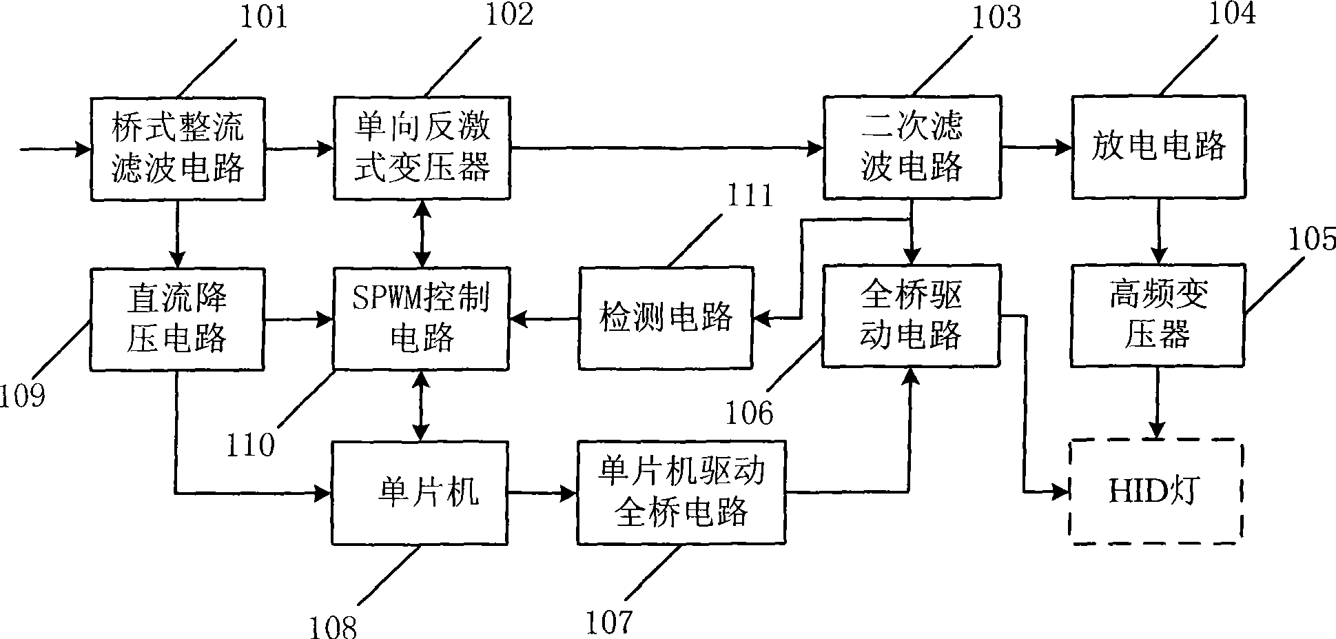
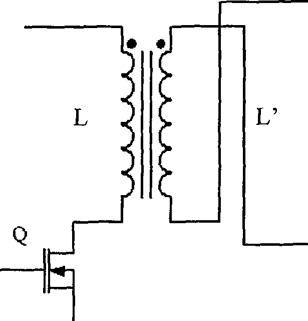
[0005] Usually, the interior of the HID lamp is full of ionized gas with positive charges, such as xenon gas, etc., and it is best to use a negative voltage for power supply, so as not to affect the service life of the HID lamp, and the unidirectional flyback transformer 102 of this technical solution (such as figure 2 As shown, the primary inductance coil L, the secondary inductance coil L and the electronic switch field effect transistor Q), can only output positive voltage and cannot output negative voltage, so the service life of the HID lamp is affected
In addition, due to the existence of the carrier ratio of the pulse signal output by the SPWM control circuit, it is difficult to increase the frequency value of the sine quantity output, and the nonlinearity of the sine quantity will also cause the existence of a large duty cycle. The power device of the SPWM control circuit The frequency characteristics are equivalent to operating in a higher frequency environment, and must be used with derating, thus limiting the system frequency, resulting in a decrease in its power factor, and the first-order system stability of the pulse signal output by the SPWM control circuit is poor, and the load response speed is slow
[0006] In summary, the existing electronic ballasts for HID lamps cannot output negative voltage suitable for HID lamps to prolong the service life of HID lamps, and the power factor of the electronic ballasts for HID lamps is low, the stability of the first-order system is poor, and the load response slow

Method used


Image

  • Electronic ballast of HID lamps
  • Electronic ballast of HID lamps
  • Electronic ballast of HID lamps

Examples


Embodiment Construction

[0027] The specific embodiment of the present invention is described in detail below in conjunction with accompanying drawing:

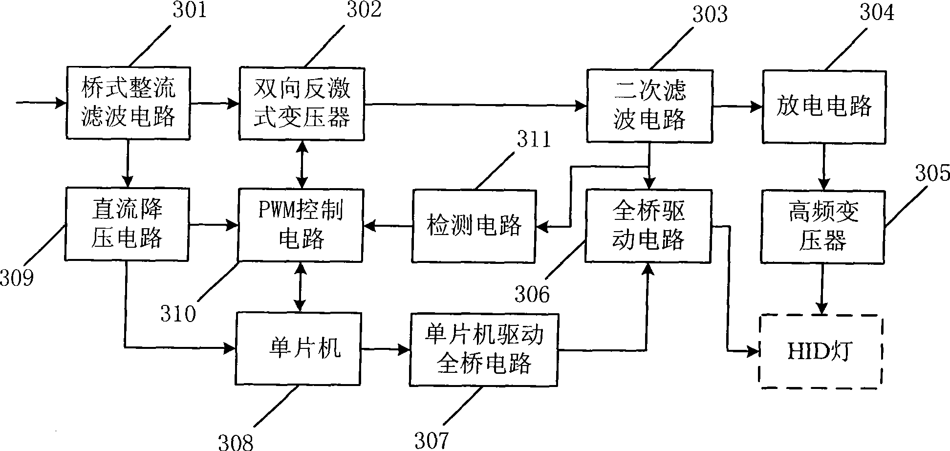
[0028] refer to image 3 , the HID lamp electronic ballast of the present invention comprises: comprise bridge type rectification filter circuit 301, secondary filter circuit 303, discharge circuit 304, high-frequency transformer 305, full-bridge driving circuit 306, single-chip microcomputer driving full-bridge circuit 307, single-chip microcomputer 308 , DC step-down circuit 309 and detection circuit 311, bridge rectifier filter circuit 301 is connected with DC step-down circuit 309, secondary filter circuit 303 is connected with discharge circuit 304, full bridge drive circuit 306, detection circuit 311 respectively, discharge circuit 304 Connect with the high-frequency transformer 305, the high-frequency transformer 305 is connected with the HID lamp, the full-bridge drive circuit 306 is connected with the single-chip microcomputer 307, the detecti...


PUM


Abstract

The invention provides an electronic ballast of HID lamps. The electronic ballast of the HID lamps employs a two-way flyback transformer capable of generating negative voltage based on the existing electronic ballast of the HID lamps to replace the one-way flyback transformer of the existing electronic ballast of HID lamps, and employs a PWM control circuit with high power factor, good first-order system steadiness and quick loading response speed to replace the SPWM control circuit of the existing electronic ballast of the HID lamps, thereby being capable of prolonging the service life of the HID lamps; moreover, the electronic ballast of the HID lamp has the advantages of high power factor, good first-order system steadiness and quick loading response speed.

Description

technical field [0001] The invention relates to an electronic ballast, in particular to an electronic ballast for an HID lamp. Background technique [0002] HID lamps (High Intensity Discharge, high-pressure gas discharge lamps), because of their high luminous efficiency, good color rendering, and stable brightness, are becoming more and more widely used in automotive lighting, home lighting, commercial lighting, and municipal lighting. Applications. HID lamps are usually controlled with HID lamp electronic ballasts. [0003] Such as figure 1 As shown, it is a structural block diagram of an existing electronic ballast for HID lamps, including a bridge rectifier filter circuit 101, a unidirectional flyback transformer 102, a secondary filter circuit 103, a discharge circuit 104, a high frequency transformer 105, Full-bridge driving circuit 106 , single-chip microcomputer driving full-bridge circuit 107 , single-chip microcomputer 108 , DC step-down circuit 109 , SPWM (Sine...

Claims


Application Information

Patent Timeline
Patent Type & Authority Applications(China)
IPC IPC(8): H05B41/288
Inventor 林忠玲杨尚明侯祥振
Owner SHANDONG HUADING WEIYE ENERGY TECH
Learn More