
Engine arrangement

A technology of engine and engine speed, applied in engine control, combustion engine, machine/engine, etc., can solve problems such as crankshaft, engine roughness, etc., and achieve the effect of reducing torque loss

Inactive Publication Date: 2009-06-10
VOLVO CAR CORP
View PDF1 Cites 10 Cited by
  • Summary
  • Abstract
  • Description
  • Claims
  • Application Information

AI Technical Summary

Problems solved by technology

Subsequent operation of the connected engine will almost certainly experience noise, vibration and harshness (NVH) problems since the relative angular position of the crankshaft is not taken into account

Method used


Image

  • Engine arrangement
  • Engine arrangement
  • Engine arrangement

Examples


Embodiment Construction

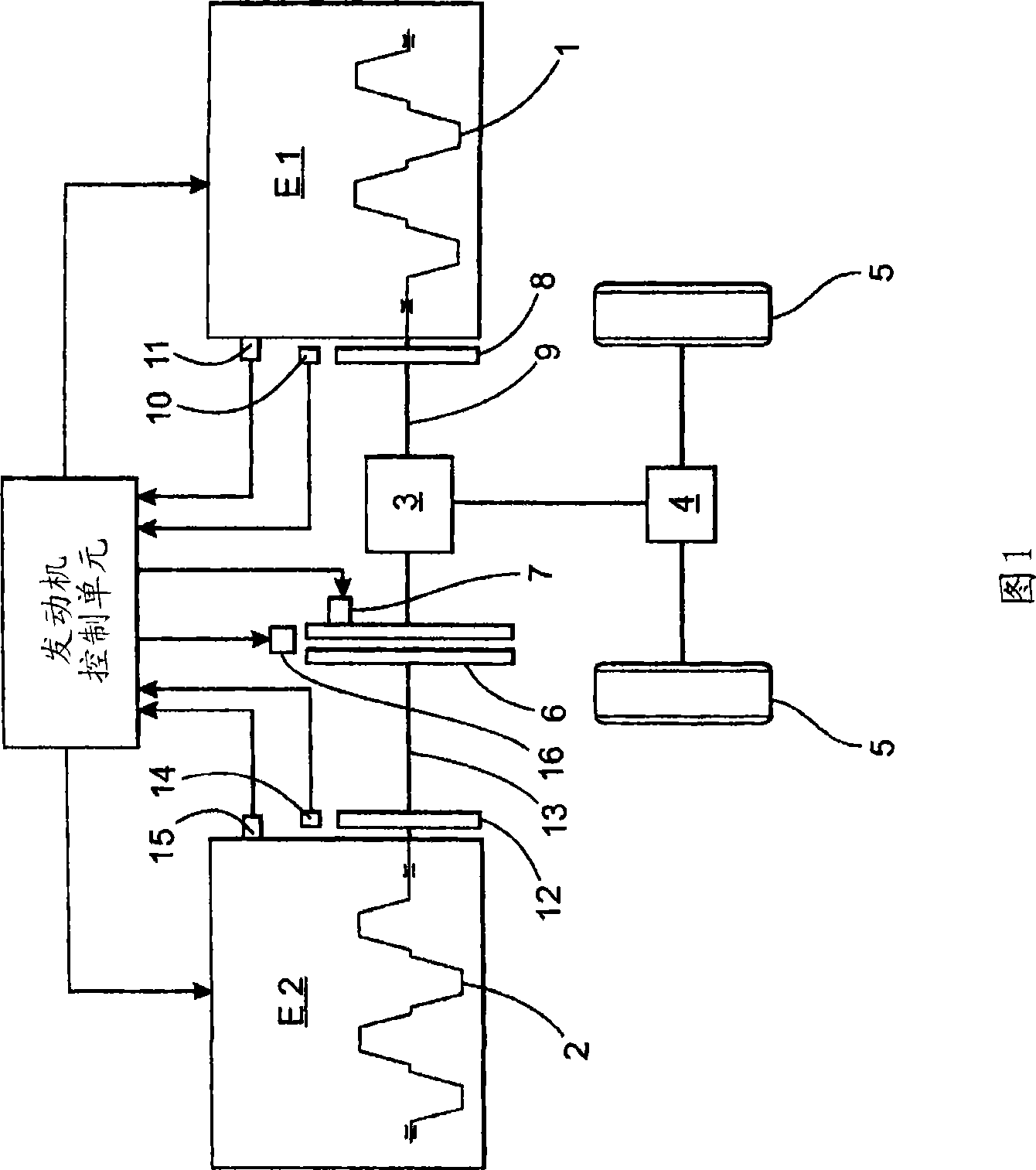
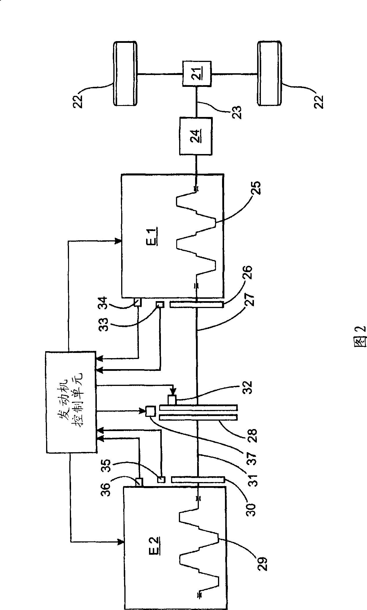
[0032]Figure 1 shows a schematic diagram of an engine arrangement according to one embodiment of the invention. The figure shows a front-wheel drive engine arrangement comprising a first and a second internal combustion engine E1 and E2 , wherein each engine comprises a crankshaft 1 , 2 . In this example, each engine E1 , E2 comprises four cylinders with pistons connected to the respective crankshaft 1 , 2 . The engine is installed in the vehicle in an in-line transverse configuration. An engine control unit (ECU) is arranged to control the first and second engines E1, E2, wherein the engine control unit (ECU) is connected to sensors to monitor a number of operating parameters of said engines. Then, an engine control unit (ECU) is provided for transmitting control signals to control the first and second engines E1, E2. The crankshaft 1 of the first engine E1 is connected to a powertrain including a gear transmission (ie, transmission) 3 and a gearbox (or transmission) 4 to t...


PUM


Abstract

The invention relates to an engine arrangement and a method for controlling the same; the engine arrangement comprising a first and a second internal combustion engine, wherein each engine comprises a crankshaft and at least one cylinder with a piston connected to said crankshaft, a controllable clutch arranged between the crankshafts, an engine control unit for controlling the first and second engine and sensors for monitoring at least one operating parameter for the said engines connected to the engine control unit. According to the invention, the relative angular position of the crankshafts of the first and second engines are controlled using a sensed crankshaft position and the ignition timing sequence of the respective first and second engines. A controllable friction clutch is used to lock up the crankshafts of the first and second engines in said at least one predetermined relative angular position.

Description

technical field [0001] The present invention generally relates to the control of an engine arrangement comprising first and second internal combustion engines, wherein each engine comprises a crankshaft, at least one cylinder with a piston connected to said crankshaft and a controllable cylinder arranged between said crankshafts. friction clutch. Background technique [0002] Engine arrangements using dual displacement engines coupled to vary the number of active cylinders within a four-stroke internal combustion engine have been considered a viable solution to reducing fuel consumption in future vehicles. [0003] US patent US 4,421,217 discloses an arrangement for connecting coaxial crankshafts to vary the number of active cylinders in an internal combustion engine. According to this arrangement, the friction clutch is operated to start and connect the crankshaft. The problem with this solution is to start the second engine by actuating a clutch driven by the first engin...

Claims


Application Information

Patent Timeline
Patent Type & Authority Applications(China)
IPC IPC(8): B60W10/06B60W10/02F02B73/00
CPCF02D31/001Y10S123/08F02D41/009F02D41/0097F02D25/04F02D25/02F02D2250/21B60K5/08
Inventor 索伦·埃里克森简·伦德格伦
Owner VOLVO CAR CORP
Learn More