Heat recovery device of controllable vehicle exhaust

A technology of heat recovery device and automobile exhaust, which is applied in exhaust devices, mufflers, mechanical equipment, etc., can solve problems such as consumption, large fuel oil, and increase air pollution, and achieve good controllability.

Inactive Publication Date: 2009-06-10
卢能晓
View PDF0 Cites 4 Cited by
  • Summary
  • Abstract
  • Description
  • Claims
  • Application Information

AI Technical Summary

Problems solved by technology

Take the preheating of a car at an ambient temperature of 0°C as an example. It takes about 5 minutes to preheat the engine at idle speed to make the water temperature reach 30°C. This process consumes a lot of fuel, and the exhaust gas also increases the pollution to the atmosphere.

Method used


Image

  • Heat recovery device of controllable vehicle exhaust

Examples


Embodiment Construction

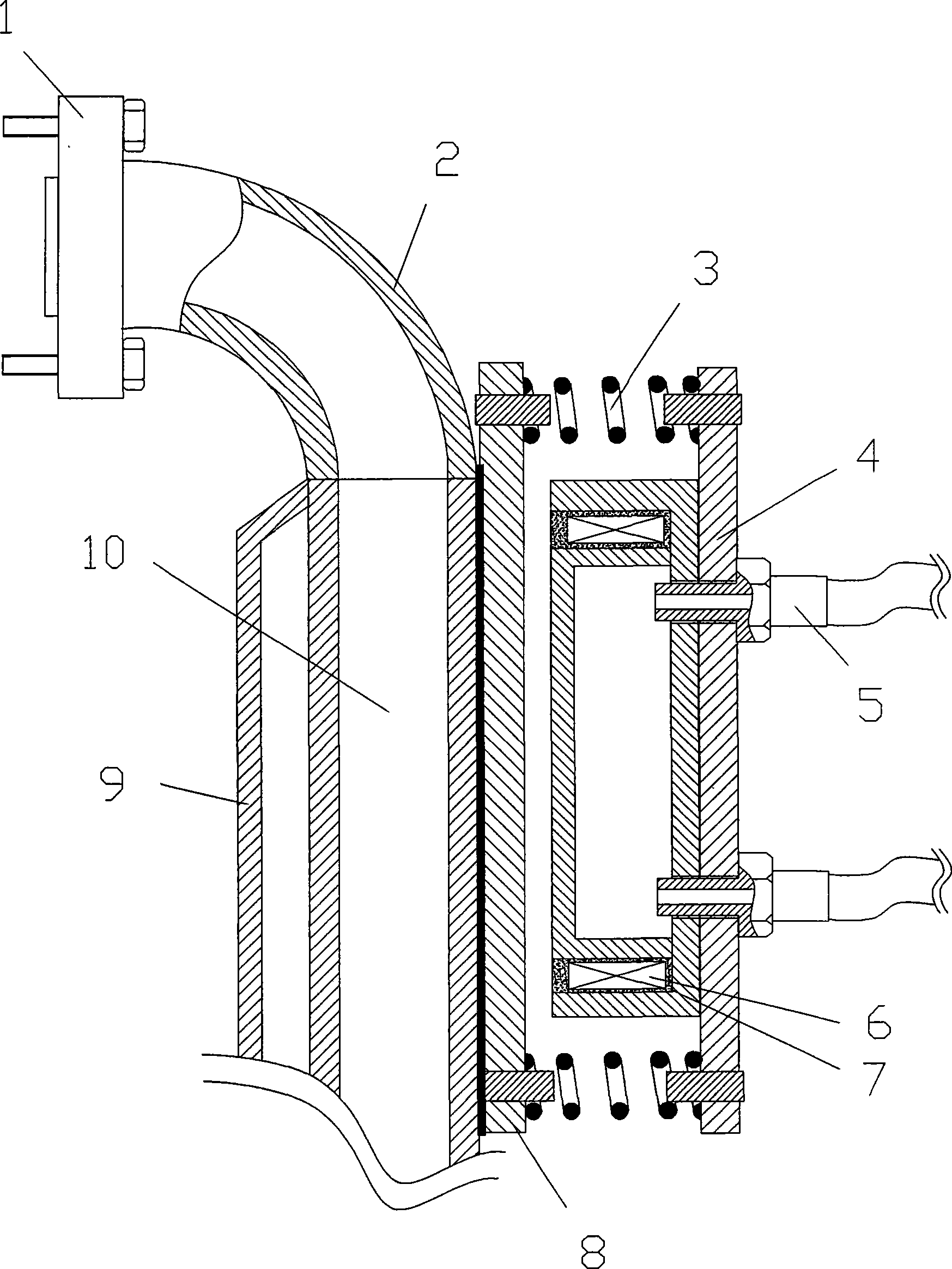
[0011] In conjunction with the accompanying drawings, the embodiment of the controllable automobile exhaust heat recovery device is to connect the waste gas box 10 in series near the exhaust pipe mouth 1 at the front of the exhaust pipe. An outer wall of the waste gas box 10 is a flat iron plate 8, and the Iron plate 8 is welded on exhaust gas box 10, and water tank 4 supports and hangs on plane iron plate 8 with spring 3, and water tank 4 and plane iron plate 8 are set up in parallel, leave the gap of 2-3mm therebetween.

[0012] The fronts of the waste gas box 10 and the water tank 4 are square, and there are four springs 3 for supporting the suspension of the water tank 4, which are distributed at the four corners of the water tank 4.

[0013] The water tank 4 is made of iron, and the circumference is slotted, and the notch faces the plane iron plate 8, and the coil 7 is embedded in the slot, and is encapsulated with the encapsulating resin 7, and the encapsulating resin ado...


PUM


Abstract

The present invention discloses a controllable automobile tail gas heat recovery device which comprises the following structure: connect a waste heat box in series on the foreside of a exhausting pipe that closes to its mouth; one ectotheca side of the waste heat box is flat iron plate; support and suspend a water tank by spring on the flat iron plate wherein the water tank is made of iron and in parallel with the flat iron plate; a groove is set on the border of the water tank and the notch of the groove facing the flat iron plate; a coil is embedded inside the groove; the side of the water tank that facing the flat iron plate is flat; and a water in-out joint is provided on the back side of the water tank. Connect the water tank of the device to the cooling water road of the engine in series, when the coil energized, the water tank attracts the flat iron plate of the waste heat box, and heat of the waste heat box passes to the water tank to heat water inside; when no heating needed, cut off power supply of the coil, then the water tank takes off the waste heat box and stops absorbing heat. The controllability of the present device is good and can be applied on automatic control.

Description

technical field [0001] The invention relates to automobiles, and is a device for collecting exhaust heat for reuse. Background technique [0002] The automobile engine is an internal combustion engine, and its output efficiency is 40%-50%. Part of the remaining energy is consumed in the work of the compression stroke, the intake and exhaust stroke, and the work of overcoming friction, and a large amount of energy is dissipated in the form of heat. , including the heating of the cylinder and the heat emitted by the exhaust gas. Within a few seconds after the engine is started in a cold car, the temperature of the exhaust pipe can exceed 100°C, and it takes a few minutes for the temperature of the cooling water to increase to the normal operating temperature of the engine. Take the preheating of a car at an ambient temperature of 0°C as an example. It takes about 5 minutes to preheat the engine at idling speed to bring the water temperature to 30°C. This process consumes a lo...

Claims


Application Information

Patent Timeline
Patent Type & Authority Applications(China)
IPC IPC(8): F02N17/04F01N5/02F02N19/04
CPCY02T10/16Y02T10/12
Inventor 卢能晓
Owner 卢能晓
Why Eureka
Try Eureka