
Driving wheel of diamond bead rope sawing machine

A technology of bead wire saw machine and drive wheel, which is applied in the field of drive wheel, can solve problems such as inability to process, and achieve the effects of convenient adjustment, strong operability, and reasonable structure

Inactive Publication Date: 2009-06-10
荣成中磊科技发展有限公司
View PDF1 Cites 2 Cited by
  • Summary
  • Abstract
  • Description
  • Claims
  • Application Information

AI Technical Summary

Problems solved by technology

[0003] In order to overcome the limitation of the groove distance of the drive wheel of the wire saw machine in the prior art and the inability to process large-scale plates with different thicknesses of multiples of 5, the present invention provides a diamond beaded wire saw drive wheel, the diamond Beaded wire saw transmission wheel is not only reasonable in structure, but also can conveniently adjust the position of the wire saw in the transmission groove according to the requirements of plate thickness, so as to achieve simultaneous processing of large plates with different thicknesses in multiples of 5

Method used


Image

  • Driving wheel of diamond bead rope sawing machine
  • Driving wheel of diamond bead rope sawing machine

Examples


Embodiment 1

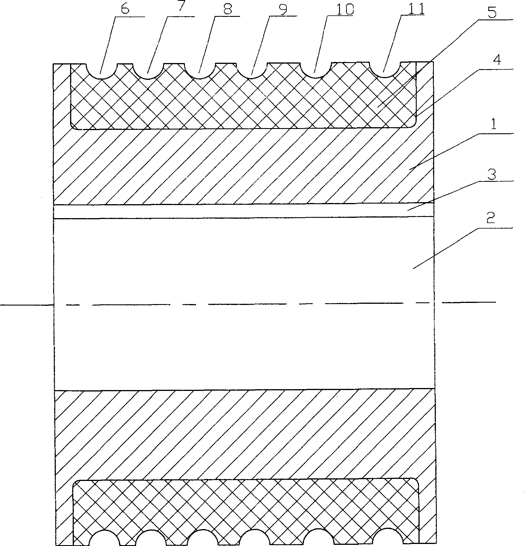
[0011] exist figure 1 Among them, a transmission wheel of a diamond beaded wire saw machine includes a transmission wheel body (1), and the transmission wheel body (1) is made of metal materials through precision casting.

[0012] A transmission shaft hole (2) is provided at the center line of the transmission wheel body (1), and a transmission keyway (3) is provided on the hole wall of the transmission shaft hole (2).

[0013] A wear-resistant overcoat (5) is embedded in the outer circular wheel groove (4) of the transmission wheel body (1). What this wear-resisting overcoat (5) adopts is polyurethane material, and one-time hot molding is embedded in the outer circular wheel groove (4) of transmission wheel body.

[0014] Offer 6 semicircular transmission grooves on wear-resisting overcoat (5) outer peripheral surface, because what generally adopt abroad at present is that diameter is 8.5mm diamond bead wire saw, so the diameter of transmission groove is 8.5mm. Such as fig...

Embodiment 2

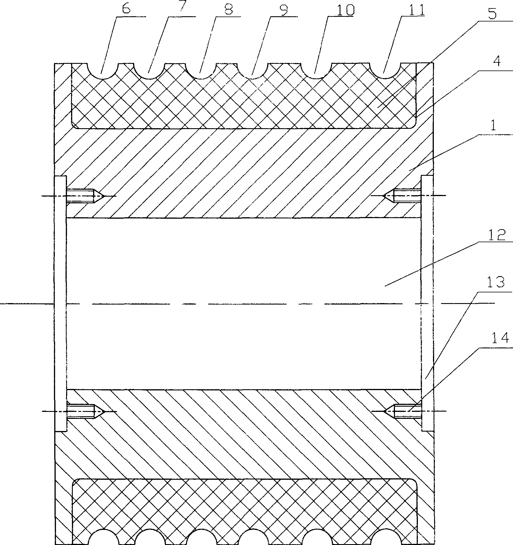
[0017] figure 2 A main cross-sectional view of the structure of another example of the present invention is given. In the figure, there is only a bearing chamber (12) at the center line of the transmission wheel body (1), and a cover plate groove ( 13) and the threaded hole (14) that is matched with the fixing screw that the fixed cover plate is used.

[0018] It should be noted that the other components and the structure of the components provided on the transmission wheel body (1) are the same as those in Embodiment 1, and will not be repeated here.

[0019] The driving wheel in this embodiment can rotate around a positioning shaft and is used as a driven driving wheel.

[0020] When the present invention is in use, as figure 1 , figure 2 As shown, diamond beaded wire saws are installed in the first transmission groove (6), the third transmission groove (8) and the fifth transmission groove (10) on the outer circumferential surface of the wear-resistant jacket (5), and...


PUM

PropertyMeasurementUnit
diameteraaaaaaaaaa

Abstract

The invention relates to a transmission wheel of a diamond wire saw, which is used in a stone cutting machine. The transmission wheel comprises a transmission wheel body, the center line of which is open with a transmission shaft hole and a transmission key groove or a bearing room, the outer ring wheel groove of the transmission wheel body is embedded and provided with a wear resistant casing, the outer peripheral plane of the wear resistant casing is open with semicircle transmission grooves of the diameter of 8.5mm, the transmission grooves are characterized in that the transmission grooves have six and are arranged from left to right, the center distance between the first transmission groove and the second transmission groove is 13.5mm, the center distance between the second transmission groove and the third transmission groove is 15mm, the center distance between the third transmission groove and the fourth transmission groove is 15mm, the center distance between the fourth transmission groove and the fifth transmission groove is 18.5mm, and the center distance between the fifth transmission groove and the sixth transmission groove is 20mm. The transmission wheel has the advantages of simple and reasonable structure, convenient use, easy regulation of the wire saw distance and high processing efficiency, and large scale of plates of different thicknesses which are multiples of 5 can be processed at the same time.

Description

technical field [0001] The invention relates to a drive wheel of a power machine, in particular to a drive wheel of a diamond beaded wire saw machine suitable for stone cutting machines. Background technique [0002] In the stone processing industry, in order to obtain large-area flat plates, diamond beaded wire saw machines are generally used. For example, the CN2784157Y Chinese utility model patent specification published on May 31, 2006 discloses a "gantry type wire saw cutting machine", including a gantry frame, a wire saw cutting mechanism and its lifting mechanism, a workbench device, a wire saw Tension control mechanism. The wire saw cutting mechanism includes wire saw wheel sets arranged on the left and right sides of the carriage. Each wire saw wheel set includes upper and lower two rotatable wire saw wheels. The wire saw is tensioned on the four wire saw wheels. . The gantry type wire saw cutting machine can easily cut large-area stone slabs at one time, but the...

Claims


Application Information

Patent Timeline
Patent Type & Authority Applications(China)
IPC IPC(8): F16H55/32B28D1/08B28D7/00
Inventor 刘新刚蒋学侨伯大顺
Owner 荣成中磊科技发展有限公司
Learn More