Fume exhaust ventilator and range integrated machine

An all-in-one machine and range hood technology, applied in the direction of removing lampblack, household stoves, household appliances, etc., can solve the problems of no obvious effect, easy penetration of condensed oil droplets, oil leakage, etc., to achieve good oil leakage prevention, low cost, good effect

Active Publication Date: 2011-09-28
ZHEJIANG MEIDA IND CO LTD
View PDF1 Cites 0 Cited by
  • Summary
  • Abstract
  • Description
  • Claims
  • Application Information

AI Technical Summary

Problems solved by technology

In addition, the stove hole needs to be erected on the top and bottom plates of the gas collection box, and the condensed oil droplets can easily penetrate into the joint between the wall surface of the stove hole and the bottom plate of the stove hole, causing oil leakage
The countermeasures of the existing gas collection box manufacturing technology are mainly to improve welding precision and reduce welding defects. Although the cost has increased a lot, there is no obvious effect. Practice has proved that welding defects are unavoidable

Method used


Image

  • Fume exhaust ventilator and range integrated machine
  • Fume exhaust ventilator and range integrated machine
  • Fume exhaust ventilator and range integrated machine

Examples


Embodiment 1

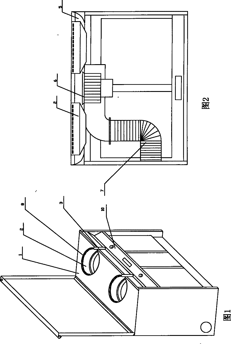
[0019] Refer to attached Figure 1-5 :

[0020] The range hood integrated machine of the present invention includes a cabinet-type body, the panel 1 of the body is provided with a concave cylindrical stove hole 2, the bottom plate of the stove hole 2 is provided with a stove 4, and the bottom of the stove hole 2 The upper part of the wall surface is provided with an arc-shaped suction port 8, and the side of the stove hole 2 facing people has a handle hole 3, the suction port 8 is covered in the gas collection box 5, and the air inlet of the fan 6 is arranged on the gas collection box. In the box 5, the wall surface of the stove hole 2 is connected with the top plate and the bottom plate of the gas collection box 5, the fan 6 is also connected with the exhaust pipe 7, and the top surface of the gas collection box 5 is attached with a The bar 12 of the junction of 11.

[0021] There is a bottom plate 9 generally parallel to the panel 1 , and the bottom plate 9 extends to the ...

Embodiment 2

[0029] Refer to attached Figure 1-7 :

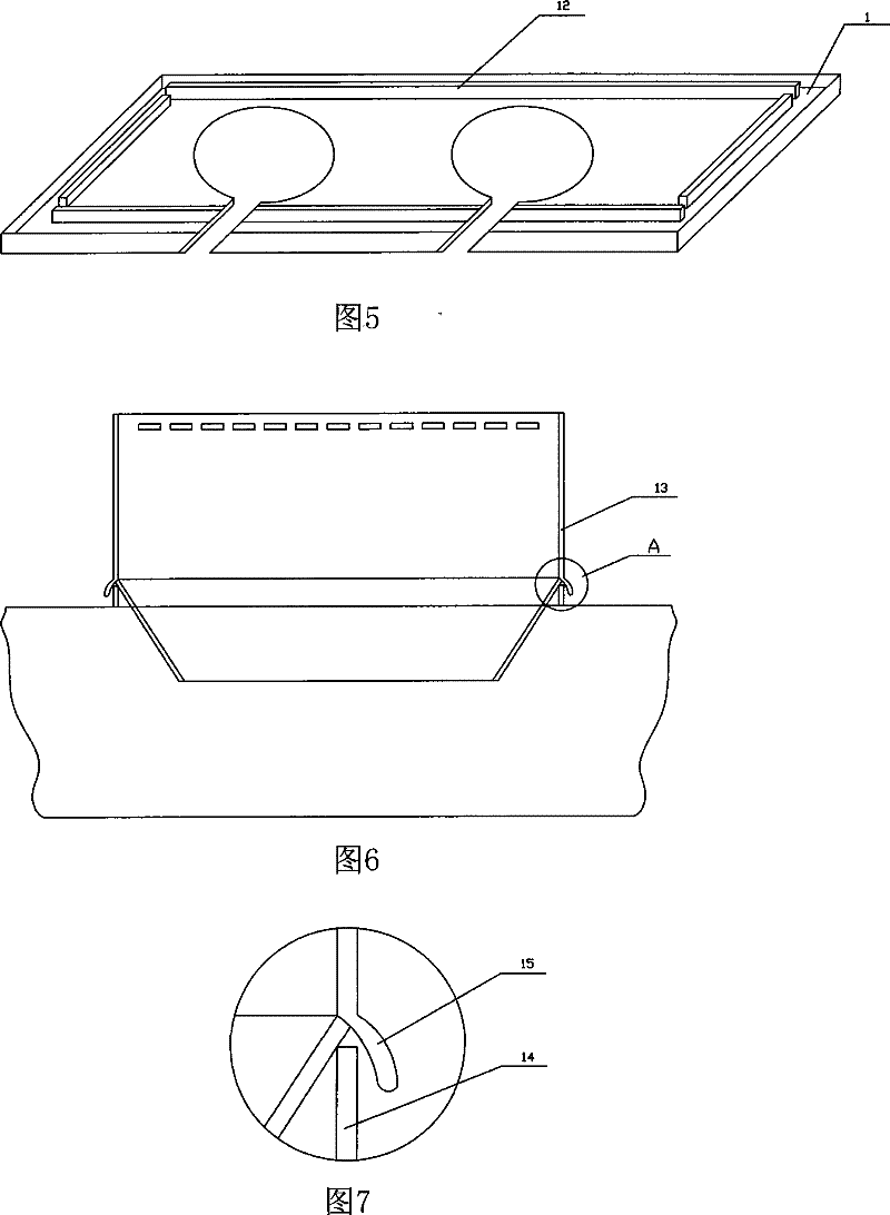
[0030] The difference between this embodiment and the second embodiment is that the following structure is added: the cylindrical wall surface 13 of the stove hole 2 is fastened with the annular flange 14 on the bottom plate 9, and the cylindrical wall surface 13 is wrapped in the The convex edge 14 is outside.

[0031] Oil droplets will also condense on the cylindrical wall surface 13 of the stove hole 2, and if the joint between the cylindrical wall surface 13 of the stove hole 2 and the bottom plate is exposed, it is also easily penetrated by oil. Adopting the structure of this embodiment can prevent the seams from contacting oil droplets and prevent leakage.

Embodiment 3

[0033] Refer to attached Figure 1-7 :

[0034] The difference between the present embodiment and the third embodiment is that the air outlet on the stove hole is added: the upper part of the wall of the stove hole 2 is provided with a positive pressure air outlet, and the air outlet is opposite to the suction port, and the air outlet is obliquely Next, the air outlet is connected to the positive pressure air source through the air duct.

[0035] The combined use of the blowing port and the suction port is conducive to the formation of a fluid envelope above the source of oil fume, improving the rate of oil fume absorption.


PUM


Abstract

The invention relates to an integrative cooking utensils of lampblack absorber and cooker, comprising a cabinet body, a plurality of cylindrical sunken stove holes are formed in the panel of the body, a cooker is provided on the soleplate of the stove holes, major arc shaped air suction ports are arranged at the at the top of the wall of the stove holes, a handle hole in one side of the stove holes faces person, a gas suction port is covered in a gas collecting tank. The air inlet of a blower is set in the gas collecting tank. The walls of stove holes are connected with the top plate of gas collecting tank and the soleplate. The blower is connected with an exhaust pipe. The top surface of the gas collecting tank is attached with a blocking bar which shades the top surface and side plate of gas collecting tank. The invention is advantaged in good fuel-leaking resistance property.

Description

(1) Technical field [0001] The invention relates to a range hood integrated machine. (2) Technical background [0002] The effect of the range hood is related to the distance from the suction port to the source of the oil fume. Generally, the range hood is an upper exhaust type. The range hood is installed above the stove. The distance from the suction port to the source of the oil fume is usually 50-100 cm. It is easy to cause oil fumes to escape, affecting human health and environmental sanitation. [0003] Chinese patent 200620113337.4 discloses a range hood integrated machine. The range hood integrated machine is a combination of the range hood and the range. , reducing the free diffusion distance of oil fume and improving the absorption rate of oil fume. The suction port is set in the gas collecting box, the oil fume in the stove hole is sucked into the gas collecting box, and the temperature drops, and the oil droplets condense on the wall of the gas collecting box, ...

Claims


Application Information

Patent Timeline
Patent Type & Authority Patents(China)
IPC IPC(8): F24C15/20
CPCF24C15/2042
Inventor 夏志生
Owner ZHEJIANG MEIDA IND CO LTD
Why Eureka
Try Eureka