Soldering apparatus

A technology of welding equipment and equipment, which is applied in the direction of welding equipment, metal processing equipment, tin feeding device, etc., and can solve the problems of reduced working hours and frequent production lines

Inactive Publication Date: 2009-06-10
PIRAAHAUSU INTERN
View PDF0 Cites 7 Cited by
  • Summary
  • Abstract
  • Description
  • Claims
  • Application Information

AI Technical Summary

Problems solved by technology

Minimizing dross formation becomes especially important with small chamber sizes, otherwise the chamber must be cleaned frequently, resulting in a significant drop in operating time for welding equipment and associated product lines

Method used


Image

  • Soldering apparatus
  • Soldering apparatus
  • Soldering apparatus

Examples


Embodiment Construction

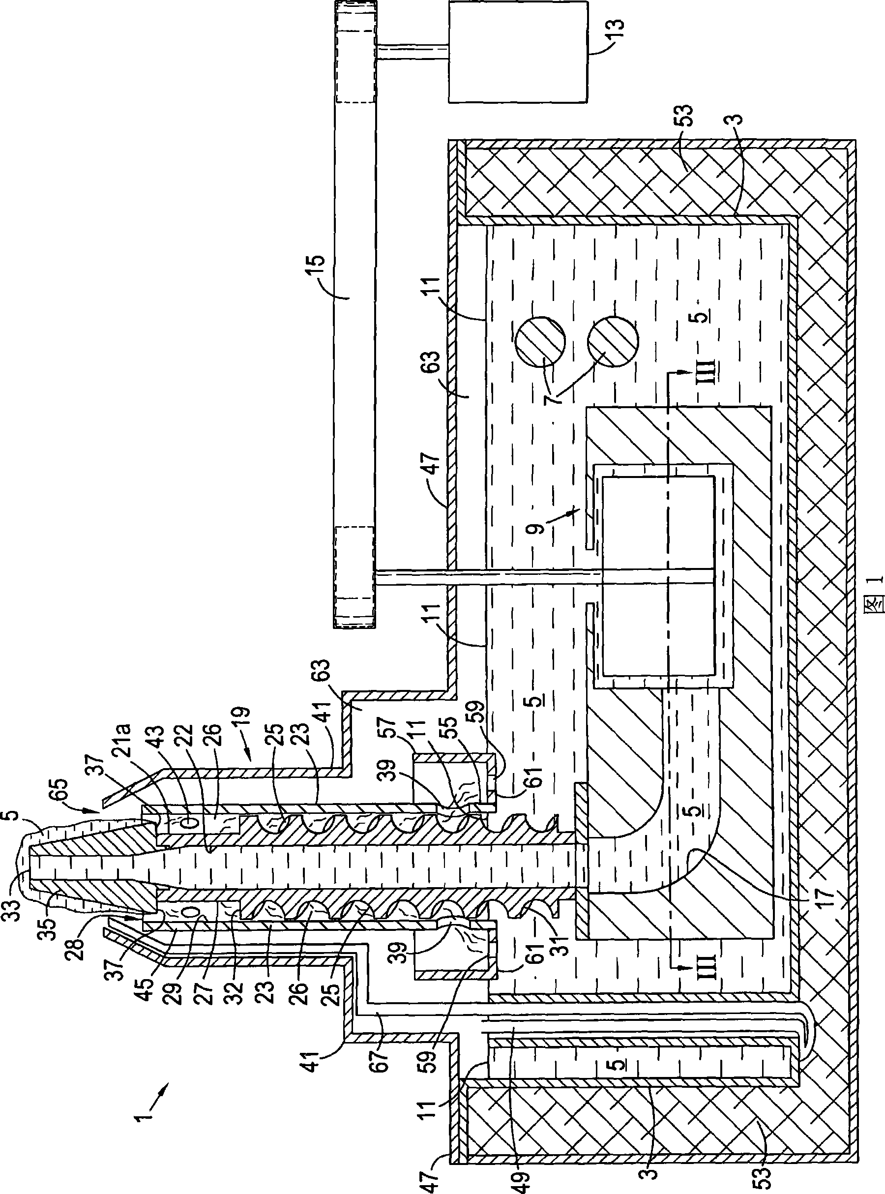
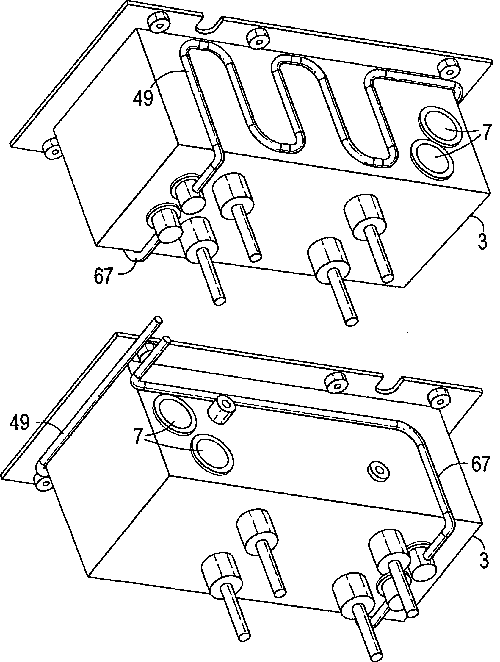
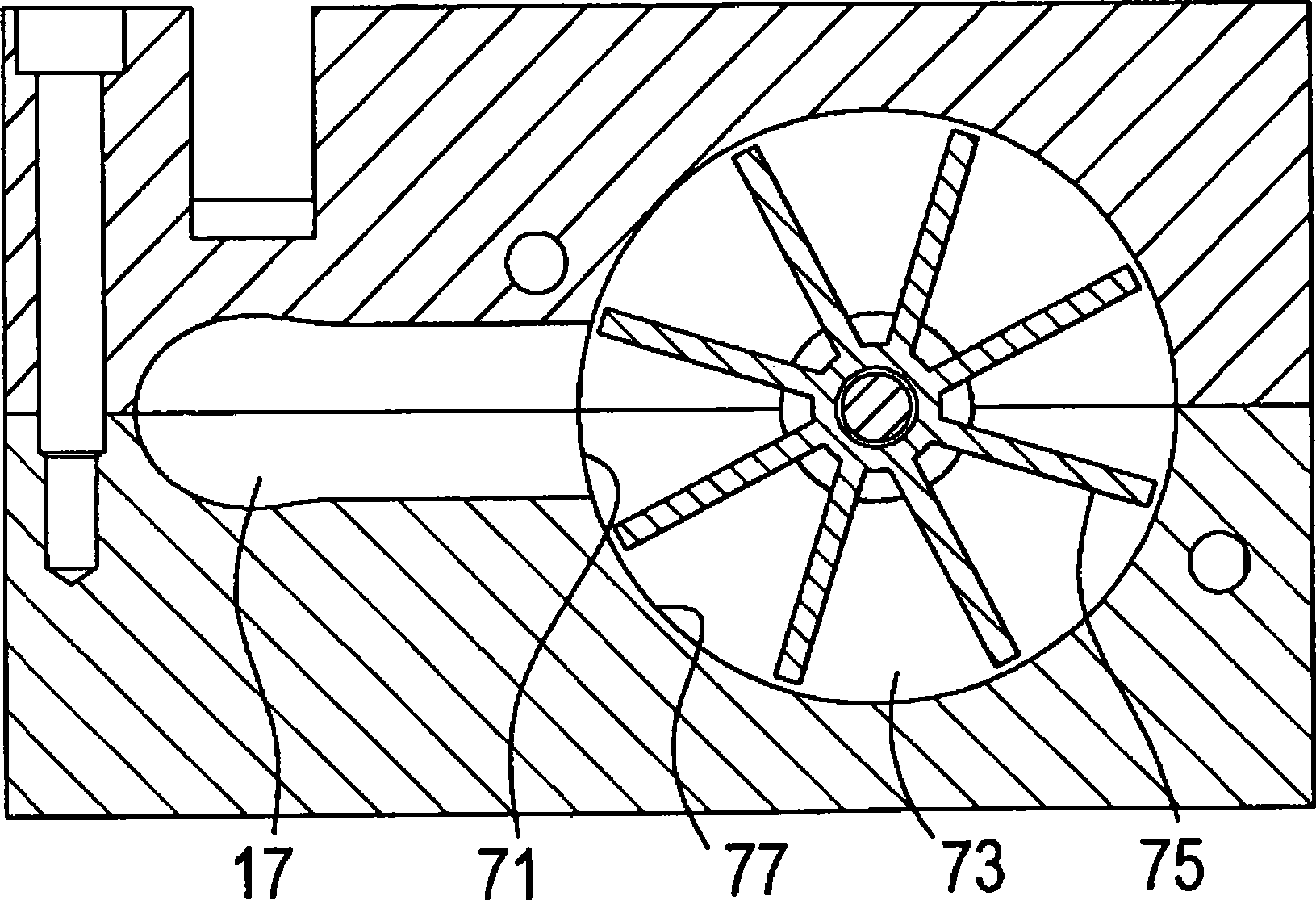
[0015] Referring to FIG. 1 , a selective soldering device 1 includes a chamber 3 for containing molten solder 5 . The solder 5 is heated by the electric heater 7 . The impeller pump 9 is accommodated in the solder chamber 3 below the upper surface 11 of the solder 5 and is driven by an electric motor 13 via a traction belt 15 . The pump 9 sucks the molten solder through the conduit 17 to the nozzle 19 .

[0016] Nozzle 19 includes a nozzle body 21 having an inner bore 22 in fluid communication with conduit 17 . The nozzle body 21 is surrounded by a sleeve 23 extending down to the solder surface 11 . Formed on an outer surface 27 of the nozzle body 21 is a helical passage 25 in a space 26 between the nozzle body 21 and the sleeve 23 . This space is open at its upper end 28 . It should be understood that the channel 25 may be formed on the inner surface 29 of the sleeve 23, or provided as a separate unit. The lower end 31 of the helical channel 25 extends down to the solder...


PUM


Abstract

A selective soldering apparatus comprises a bath (3) for molten solder (5), a solder nozzle (19) and a pump (9) for pumping molten solder (5) through the nozzle (19). The nozzle has a nozzle body (21) with an inner bore (22) through which solder is pumped to overflow a nozzle outlet (33). A jacket (23) provided around the nozzle body (21) to form an enclosed space (26) open at its upper end (28) to solder which has overflowed from the nozzle outlet (33) and the cover lower end being adjacent the surface (11) of molten solder in the bath, wherein a spiral pathway (25) is provided in the enclosed space (26) so that the overflowed solder runs down the pathway into the solder bath (3). A port (39) is provided at the lower end of the jacket for gas to flow into or out of the spiral pathway so that the pathway can be purged of air when solder is not flowing through the pathway.

Description

technical field [0001] The present invention relates to a welding device, in particular to a nozzle for a selective welding device. Background technique [0002] In known selective soldering equipment, solder is sucked from a chamber of molten solder to the outlet of a nozzle, and the component leads on the printed circuit board are dipped into the solder to solder them to the tracks of the printed circuit board. Solder can be drawn to the overflow nozzle outlet, back into the solder chamber. The suction speed can be varied to adjust the height of the solder at the nozzle outlet. The suction speed may be increased intermittently to clean or clear the solder surface at the nozzle outlet. It is also possible to reduce the suction speed or stop the suction to lower the solder surface, for example by pulling the solder away from the wire when retracting the wire from the solder. [0003] Manufacturers need to weld in a nitrogen atmosphere with very low oxygen content. This i...

Claims


Application Information

Patent Timeline
Patent Type & Authority Applications(China)
IPC IPC(8): B23K1/08B23K3/06H05K13/04
CPCB23K1/085B23K3/0653
Inventor M·图姆斯
Owner PIRAAHAUSU INTERN
Why Eureka
Try Eureka