Air particles removing device and method thereof

A technology for removing devices and particles, applied in separation methods, dispersed particle separation, cleaning methods and utensils, etc., can solve problems such as difficulty in cleaning, easy attachment of pollution sources, and incomplete consideration of pollution source attachment.

Inactive Publication Date: 2009-06-17
ACXING INDAL CO LTD
View PDF6 Cites 8 Cited by
  • Summary
  • Abstract
  • Description
  • Claims
  • Application Information

AI Technical Summary

Problems solved by technology

On the basis of the aforementioned patent No. 095106448, the inventor of this case also found that the pollution source is easy to attach near the suction port of the exhaust hood or on the wall of the exhaust pipe, which makes the subsequent cleaning quite inconvenient, and then proposes the present invention after int

Method used


Image

  • Air particles removing device and method thereof
  • Air particles removing device and method thereof
  • Air particles removing device and method thereof

Examples


Embodiment Construction

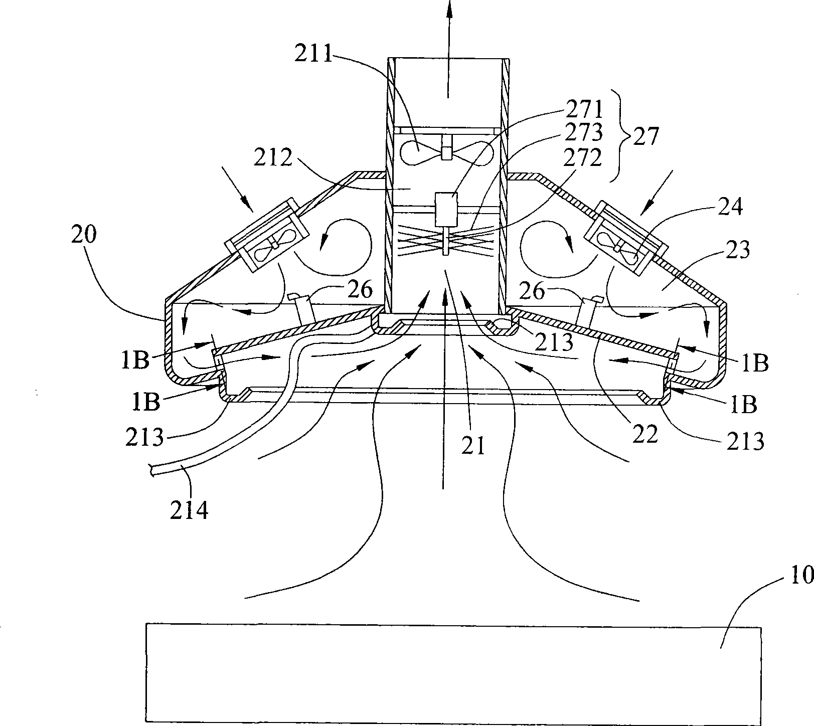
[0036] According to the air particle removal device disclosed in the present invention and its method, it is applied to the exhaust hood used as smoke removal, such as laboratories, workshops or kitchens, etc., which have pollution sources and can be used to remove the exhaust interface of the smoke. technology disclosed in the present invention.

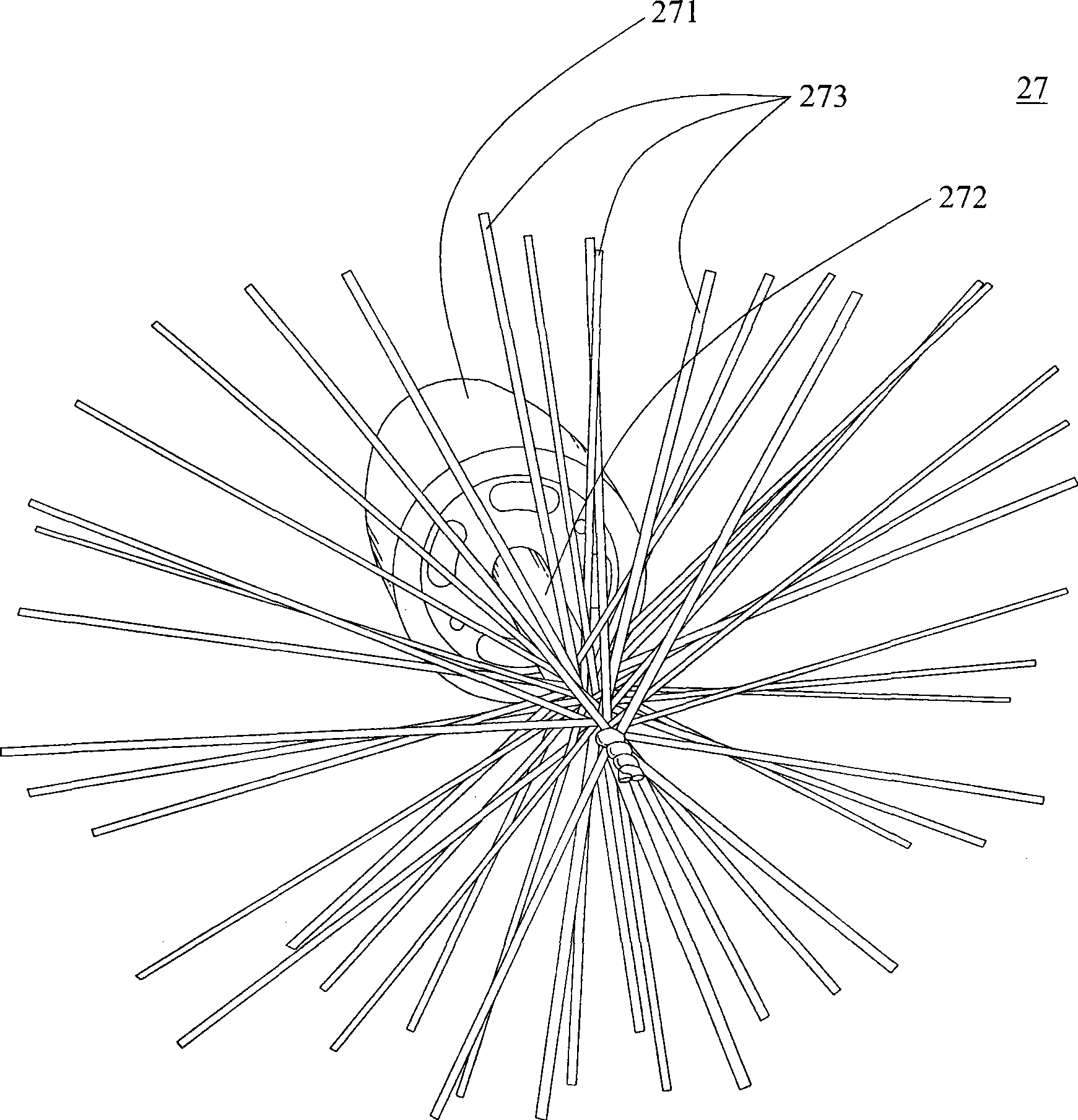
[0037] see Figure 1A , Figure 1B and Figure 1C Shown is the first embodiment of the air particle removal device of the present invention, which includes an exhaust hood 20 , an air blower 24 , an ultrasonic water mist generator 26 and a water mist thrower 27 . This air particle removal device utilizes an air extractor 211 to discharge a pollution source from a workbench 10 and filters out a pollution source sucked into the exhaust hood 20 .

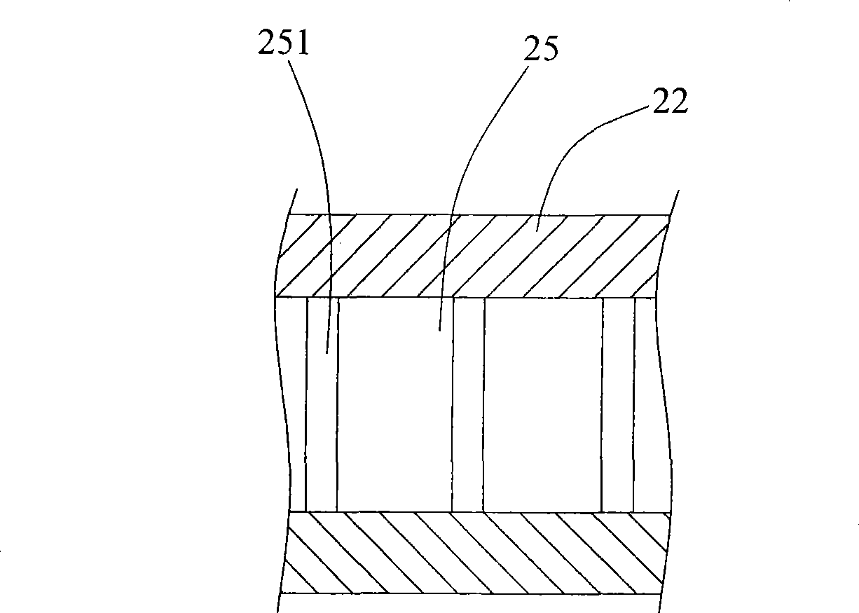
[0038] see again Figure 1A and Figure 1BAs shown, the exhaust hood 20 is arranged corresponding to the workbench 10 . The exhaust hood 20 includes an air inlet 21 , an exhaust channel ...


PUM


Abstract

The invention discloses a device and a method for discharging air particles. A pollution source is discharged out of a working table by an air pump. The device comprises an exhaust hood, an air feeder, an ultrasound water fog generator and a water fog removing machine. The exhaust hood is arranged corresponding to the working table and provided with an air suction port and an air deflector. The air feeder generates air current flowing along the air deflector towards the air suction port so as to guide the pollution source to flow towards the air suction port and be discharged by the air pump, thereby improving the effect of collecting the pollution source by the exhaust hood. The ultrasound water fog generator generates water fog adsorbing the pollution source on the flowing route of the air current, and the water fog removing machine can remove the water fog and the pollution source in the air current so as to prevent the pollution source from adhering to the exhaust hood.

Description

technical field [0001] The invention relates to a device for removing air particles and a method thereof, in particular to an device for removing air particles and a method for removing air particles used in workplaces, and can prevent smoke from adhering to the surface of the device. Background technique [0002] At present, in workplaces with pollution sources such as lampblack, factory solder area, organic solvents, lead, dust or specific chemical substances, most of them are equipped with local exhaust devices around the workbench to maintain human health according to the actual situation. The exhaust device is usually equipped with an exhaust hood corresponding to the workbench. Whenever the pollution source is attracted by the exhaust hood and flows upwards, although the exhaust hood has a strong suction and exhaust, most of the pollution sources will be sucked out, but it will also be due to Suction and discharge of pollution sources will cause upward and outward diff...

Claims


Application Information

Patent Timeline
IPC IPC(8): B01D47/06B01D45/16B08B15/04F24F7/007F24C15/20
Inventor 李水源裴培鑫
Owner ACXING INDAL CO LTD
Why Eureka
Try Eureka