

Method for producing coated plasticized screw
A technology of plasticizing screw and coating layer, applied in coating, pressure inorganic powder coating, metal material coating process and other directions, can solve the problems of affecting stress structure, layer damage, disadvantage, etc., to avoid heat transfer, improve wear and tear problem, the effect of eliminating internal stress
Inactive Publication Date: 2009-06-17
ENGEL AUSTRIA
View PDF2 Cites 2 Cited by
- Summary
- Abstract
- Description
- Claims
- Application Information
AI Technical Summary
Problems solved by technology
Multiple heating processes are necessary here, wherein in particular the melting of the alloy and the base material takes place through localized heating effects, which can adversely affect the stress structure in the material composite and bring about a structural transformation of the martensite near the surface danger
Since in addition the melting takes place in a horizontal position in the direction of rotation with simultaneous rotation of the plasticizing screw, warping is to be expected, which leads to straightness errors of the screw and thus necessitates a straightening process, which due to Formation of cracks leading to layer damage
Method used
View moreImage
Smart ImageViewing Examples

Examples
Embodiment Construction
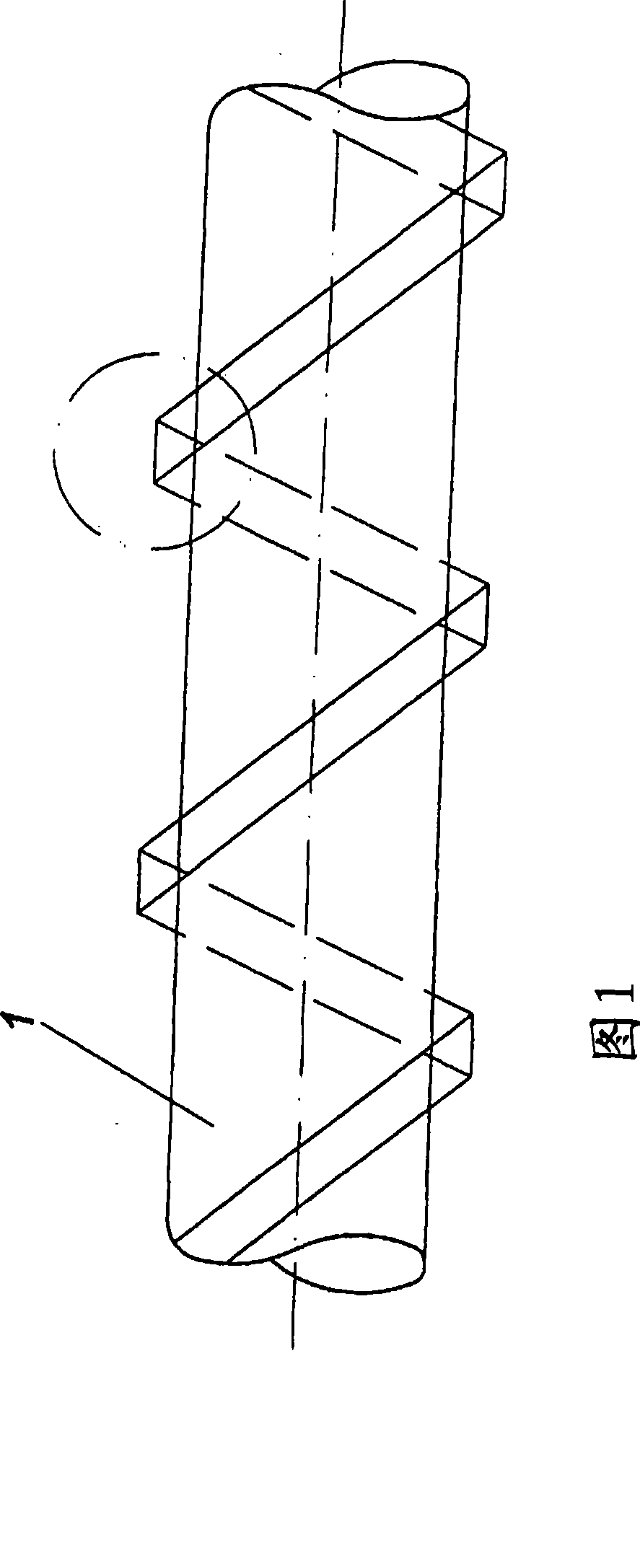
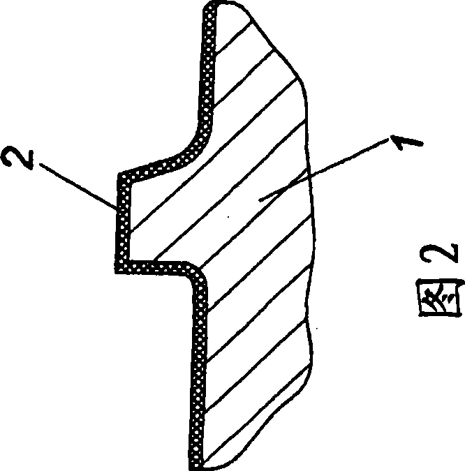
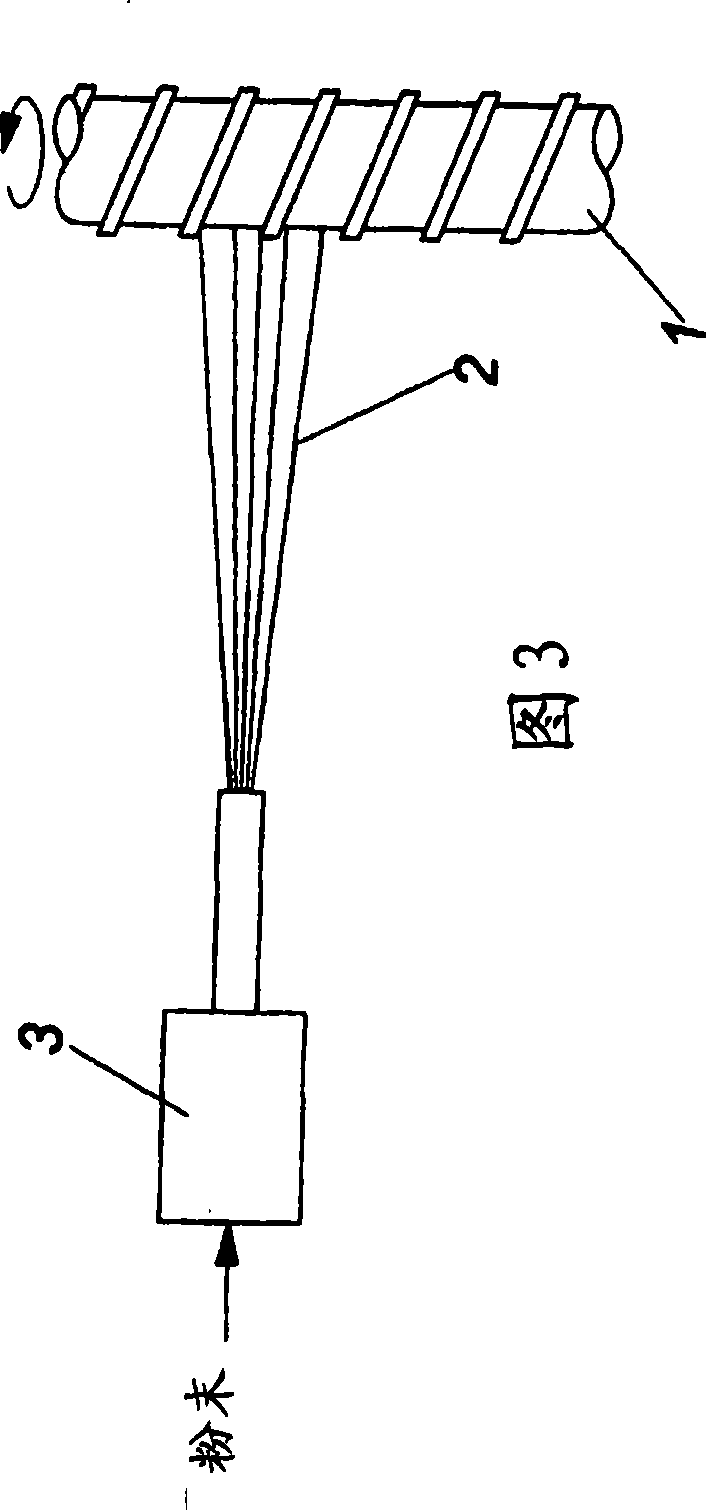
[0022] FIG. 1 shows a plasticizing screw 1 according to the invention in a side view. Parts marked with circles are shown in Figure 2 in a detailed view. Here the expelled Alloy 2 can be seen. FIG. 3 shows schematically the process of coating the plasticizing screw in side view. In an embodiment of the method according to the invention, the alloy 2 is fed in powder form to the burner 3 and then sprayed onto the rotating plasticizing screw. The gas supply for the burner that is preferably used is additionally described in the plan view in FIG. 4 .
Login to View More PUM
| Property | Measurement | Unit |
|---|---|---|
| diameter | aaaaa | aaaaa |
Abstract
The invention relates to a method for producing coated plasticizer screws for injection molding or extrusion of plastics comprises coating at least the worn-out surfaces of the plasticizer screws (1) subject to wear with a metal alloy (2); heating the coated plasticizer screws (1) for melting the metal alloy (2) and the plasticizer screws (1); cooling the coated plasticizer screws (1). All the worn-out surfaces to be coated are simultaneously heated above the melting point of the alloy (2).
Description
technical field [0001] The invention relates to a method for the manufacture of a coated plasticizing screw for injection molding or extruding plastics, wherein at least the wearing surface of the plasticizing screw is coated with a metal-based alloy, comprising the steps of: at least Alloy cladding for wear surfaces; plasticizing screw for heating the coating to melt the alloy and plasticizing screw; plasticizing screw for cooling the coating. Background technique [0002] Due to the high material stresses, for example in the case of conveying, pressing and melting plastics in injection molding and extrusion methods, the plasticizing screws used there are subject to high wear and thus only have a limited lifetime. The increase in service life is achieved by coating the wearing surfaces with metal-based alloys, as described, for example, in EP 0 542 631 . The method used there to apply a nickel-based alloy comprising diamond particles dispersed in a matrix of the alloy is u...
Claims
Login to View More Application Information
Patent Timeline
 Patent Type & Authority Applications(China)
IPC IPC(8): C23C4/12B29C48/08
CPCB29C47/0021C23C24/04B29C45/60C23C4/18C23C4/02B29C47/60B29C48/08
Inventor H·贝格尔-施泰纳J·米特曼斯格鲁贝尔G·珀克尔
Owner ENGEL AUSTRIA