Spring stiffness adjustable tuning quality damper

A technology of tuning mass and spring stiffness, which is applied in the direction of spring/shock absorber, shock absorber, solid shock absorber, etc., can solve the problem of difficult machining of spring stiffness, rough method of changing tuning mass, waste of materials and manpower And other problems, to achieve the effect of perfect vibration reduction, simplify the difficulty of adjustment work, and reduce the production cost

Active Publication Date: 2009-06-17
尹学军 +1
View PDF1 Cites 176 Cited by
  • Summary
  • Abstract
  • Description
  • Claims
  • Application Information

AI Technical Summary

Problems solved by technology

However, the existing tuned mass dampers adjust the natural frequency by replacing the spring or changing the tuning mass, such as the directional vertically adjustable tuned mass damper disclosed in the Chinese patent application number 200410087664.2, however, relying on the replacement The spring method to solve such problems will inevitably lead to a great waste of materials

Method used


Image

  • Spring stiffness adjustable tuning quality damper
  • Spring stiffness adjustable tuning quality damper
  • Spring stiffness adjustable tuning quality damper

Examples


Embodiment 1

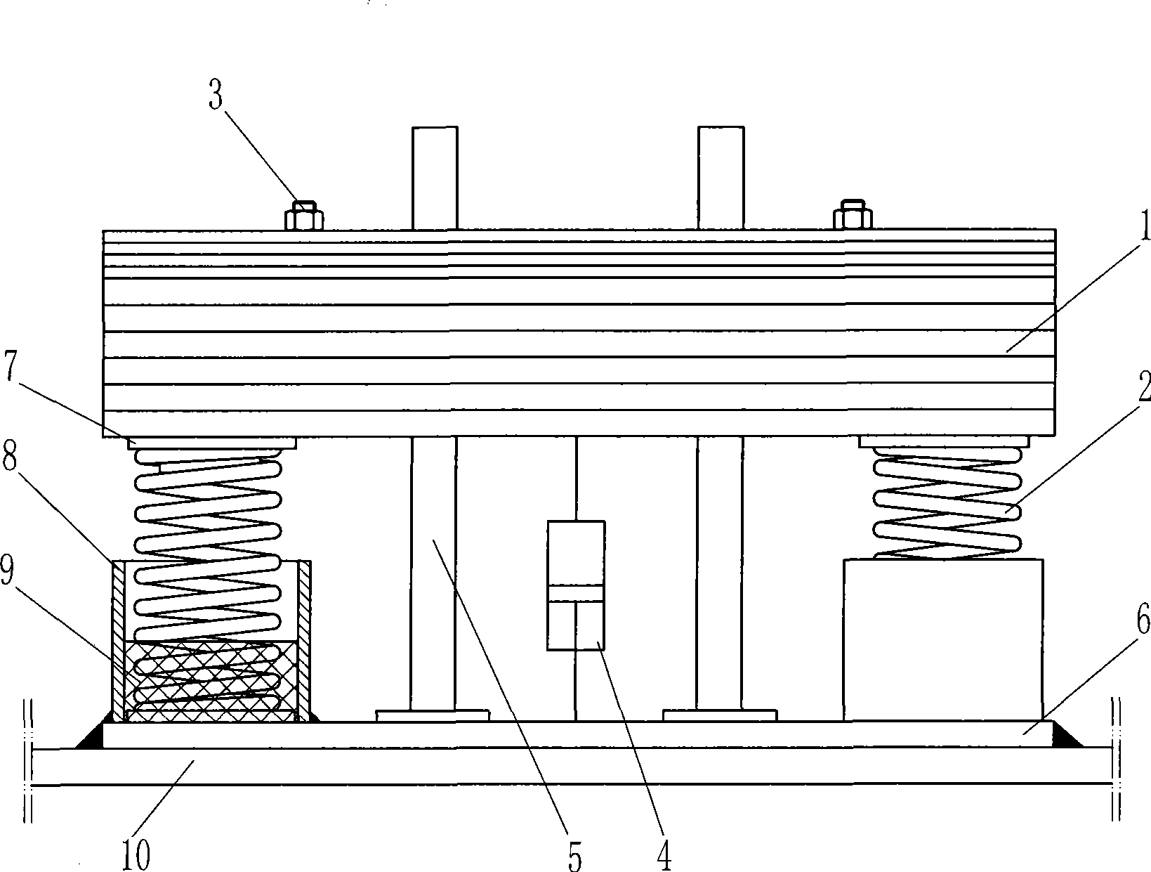
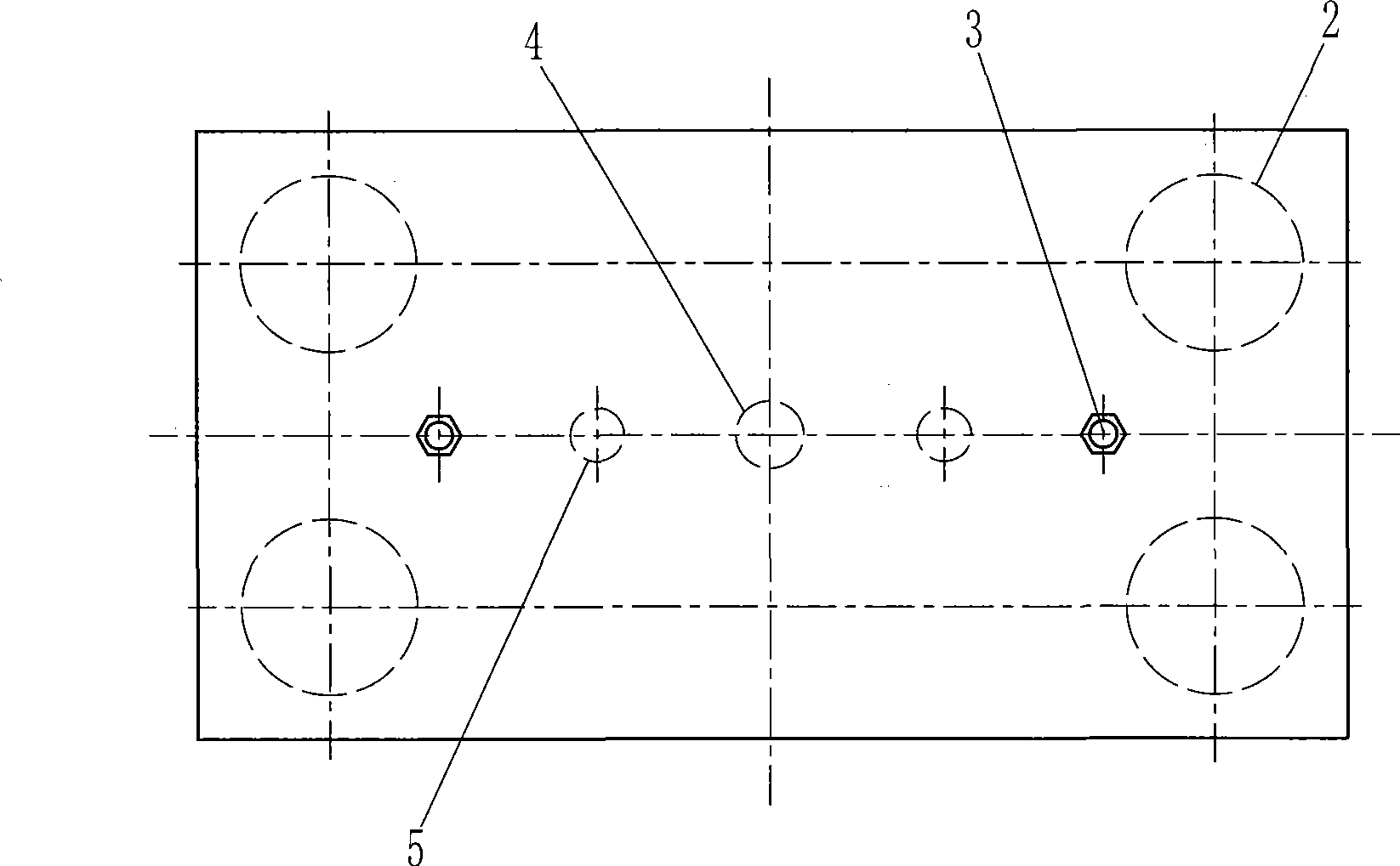
[0022] Such as figure 1 , figure 2 The spring rate adjustable tuned mass shock absorber of the present invention shown includes a tuned mass 1, four springs 2, a damper 4, and a base 6. The spring 2 is a coiled steel spring. In order to facilitate the positioning of the spring, the base 6 A spring positioning seat 7 is welded to the adjacent mass block of the spring 2. In order to facilitate accurate adjustment of the natural frequency of the adjustable spring stiffness tuned mass damper of the present invention, a stiffness adjustment device is also provided at the lower end of the spring 2. The stiffness adjustment device includes a curing cylinder 8 and a curing material 9 arranged in the curing cylinder. The material is metallic lead. Utilizing the characteristics of low melting point of metal lead and solidification at room temperature, the lead is melted into lead water and injected into the solidification cylinder to solidify it with the immersed spring part. In this way,...

Embodiment 2

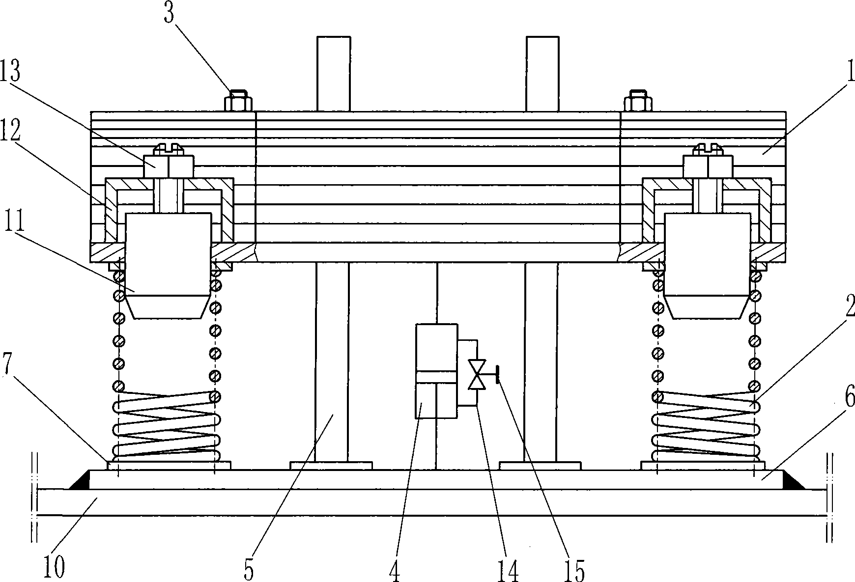
[0028] Such as image 3 , Figure 4 As shown, the difference from the first embodiment is that the stiffness adjusting device adopts a restraining block 11 inserted into the spring 2 from above, and the restraining block 11 is connected with the bracket 12 welded on its adjacent mass by a threaded structure, and is locked with a nut 13 . Since the restraining block 11 and the inner ring of the spring 2 adopt an interference fit, the elasticity of the spring section contacting the restraining block 11 is bound to be greatly restricted. In this way, the stiffness of the spring can be artificially controlled by adjusting the depth of the restraining block 11 inserted into the spring. Furthermore, the purpose of controlling the natural frequency of the spring-stiffness-adjustable tuned mass damper of the present invention is achieved. In addition, in order to facilitate the adjustment of the system damping ratio, a communication pipeline 14 is provided between the chambers at both end...

Embodiment 3

[0032] Such as Figure 5 The difference between the spring stiffness adjustable tuned mass damper of the present invention and the second embodiment is that the stiffness adjustment device adopts a restraining block 11 screwed into the spring 2 from above, and the spring 2 is arranged on the surface of the restraining block 11. The spiral protrusion 16 corresponds to the gap between the spring wires. After the constraining block 11 is screwed into the spring, the protrusion 16 on the surface of the constraining block is caught between the spring wires, so that the spring elasticity of the screwed-in section is lost, thereby realizing the function of changing the spring stiffness. The restraining block 11 is connected with the bracket 12 welded on the adjacent mass block by a threaded structure and locked with a nut 13. In addition, the damper used in this example is an adhesive damper composed of a damping cylinder 21, an adhesive damping fluid 23 (herein, silicone oil), and a pis...


PUM


Abstract

The invention specifically relates to a mass tuned vibration reducer used for controlling the vibration of an aerobridge in the airport, a large-span pedestrian bridge, a port trestle, high-rise buildings and the related structures. The mass tuned vibration reducer comprises a mass block, a spring, a damper and a base; wherein, the spring can be a spiral spring, a disc spring or a plate spring, and the end part of the spring is provided with a rigidity regulating device. The mass tuned vibration reducer can successfully realize the regulation on the natural frequency of a TMD system under the condition of needing not to assemble and disassemble the TMD since the end part of the spring is provided with the rigidity regulating device, so as to simplify the difficulty of regulation work, avoid the waste of manpower and materials and greatly reduce the construction cost. Meanwhile, the natural frequency and the damping of the system can be regulated in an optimized way under the condition of needing not to assemble and disassemble the TMD, thereby better exerting the vibration absorption performance of the mass tuned vibration reducer, ensuring safety and stableness of the pedestrians and vehicles on the large-span bridge and the thin and high building, contributing to prolonging the service lives of the thin and high building and the bridge, and having remarkable economic and social benefits.

Description

Technical field [0001] The invention belongs to the technical field of civil engineering structure vibration reduction, and specifically relates to a tuning mass vibration damper for controlling vibration of airport boarding bridges, long-span pedestrian bridges, port trestle bridges, high-rise buildings and related structures. Background technique [0002] With the development of urban construction, a variety of high-rise, super high-rise buildings, slender structures, and large-span buildings are increasing. At the same time, the urban transportation network is becoming more and more developed. Various large-span airport boarding bridges, pedestrian bridges, and ports Bridge structures such as trestle bridges have been widely used, bringing great convenience to people's travel. However, although the strength and rigidity of such slender and tall buildings and bridges are relatively easy to meet the design requirements, their vertical vibration frequency is generally relatively ...

Claims


Application Information

Patent Timeline
IPC IPC(8): E04B1/98F16F9/30F16F9/32
Inventor 尹学军
Owner 尹学军
Why Eureka
Try Eureka