Constant velocity universal joint drive spindle assembly clearance test stand

A technology of constant velocity universal joints and drive shafts, which is applied in the field of mechanisms in the field of automotive engineering technology, and can solve the problems of not testing workpieces with different structures or lengths, not testing the axial clearance of fixed ends, and not reflecting the circumferential clearance of components, etc. , to achieve the effect of simple structure, wide application range and convenient operation

Inactive Publication Date: 2009-06-17
SHANGHAI JIAO TONG UNIV +1
View PDF0 Cites 32 Cited by
  • Summary
  • Abstract
  • Description
  • Claims
  • Application Information

AI Technical Summary

Problems solved by technology

However, these two methods contain some unstable factors
First, for the axial clearance, the test data in this paper are measured by the micro-displacement sensor after eliminating the displacement of the slip end. This test method is easy to introduce other errors, because the measurement accuracy is related to the position and displacement accuracy; there is no Test the axial clearance of the fixed end, and the clearance that affects the axial use is mainly the axial clearance of the fixed end; second, for the circumferential clearance, the handwheel is used in the test, this test method is unstable, and the test results may contain artificial factor; and only for the fixed end to test, this clearance is not the assembly circumferential clearance and cannot reflect the circumferential clearance of the entire component, while the constant velocity universal joint drive shaft is installed on the car, it is the assembly circumferential clearance that affects the movement and product quality
Finally, the paper does not state whether it is possible to test artifacts of different structures or lengths

Method used


Image

  • Constant velocity universal joint drive spindle assembly clearance test stand
  • Constant velocity universal joint drive spindle assembly clearance test stand
  • Constant velocity universal joint drive spindle assembly clearance test stand

Examples


Embodiment Construction

[0026] Below in conjunction with accompanying drawing, the embodiment of the present invention is described in detail: present embodiment is carried out under the premise of technical solution of the invention, has provided detailed embodiment and specific operation process, but protection scope of the present invention is not limited to the following the embodiment.

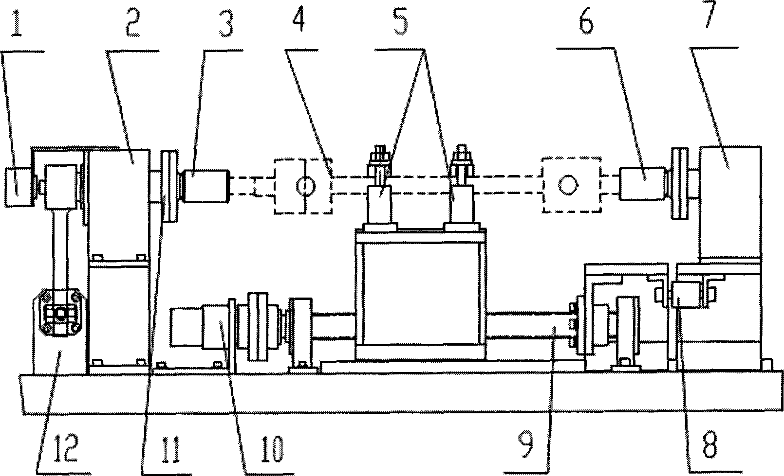
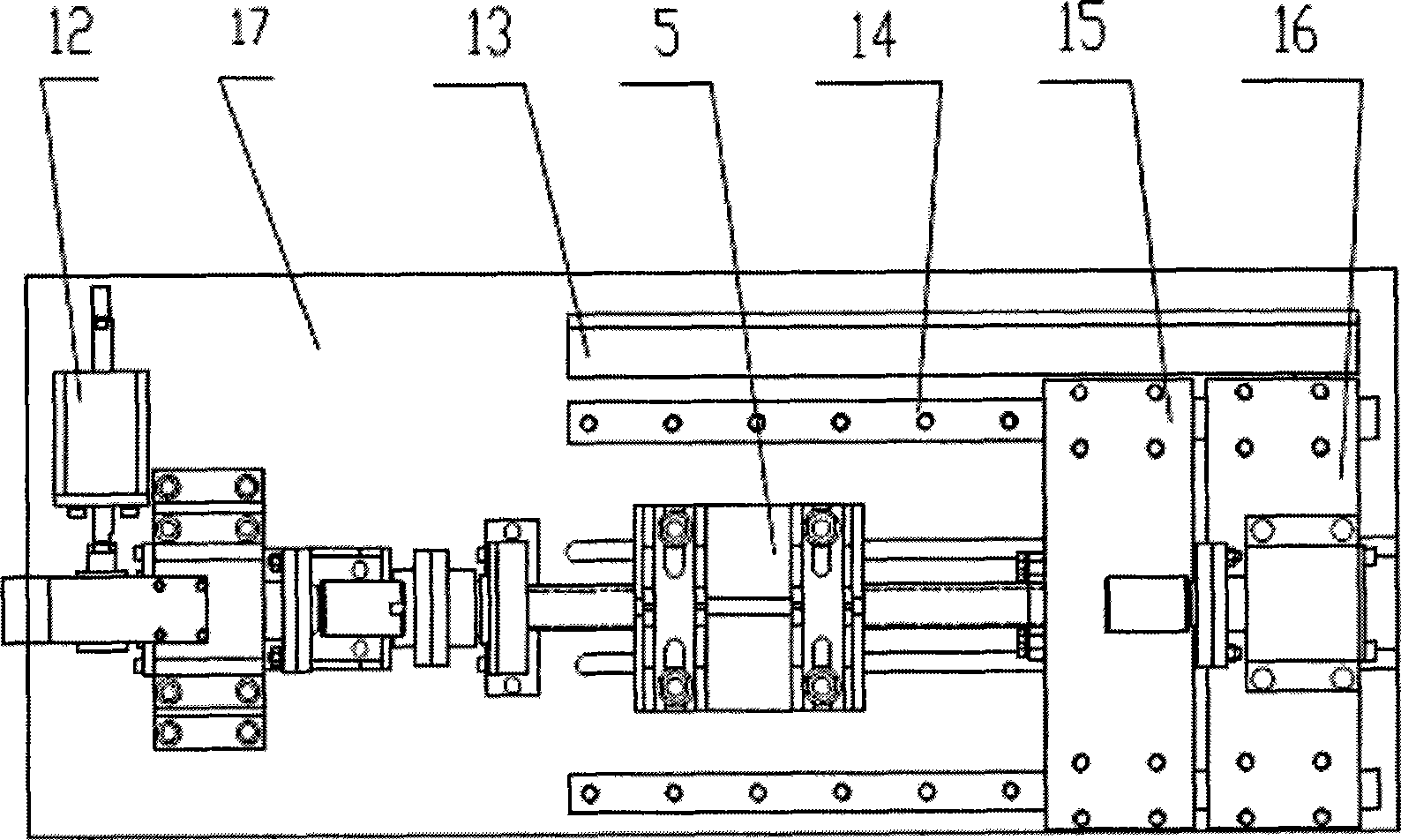
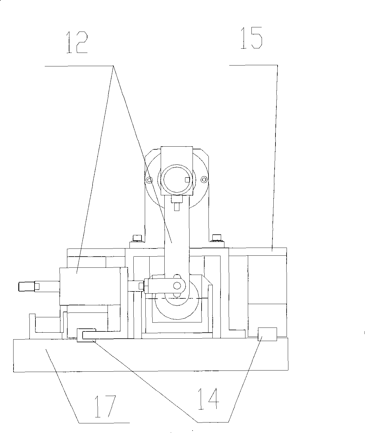
[0027] Such as figure 1 , 2 As shown in and 3, this embodiment includes: an angle sensor 1, a circumferential clearance test bearing seat 2, a circumferential clearance test chuck 3, a fixture 5, an axial clearance test chuck 6, an axial clearance test bracket 7, and a tension pressure sensor 8 , linear transmission assembly 9, motor 10, circumferential gap test spindle 11, torque force assembly 12, displacement sensor 13, guide rail 14, front slide plate 15, rear slide plate 16, frame 17. Wherein: the angle sensor 1 and the circumferential clearance test chuck 3 are arranged respectively at the tail and the h...


PUM


Abstract

The invention relates to a clearance testing table for a uniform-speed universal joint driving shaft assembly in the technical field of automotive engineering. An angle sensor and a circumferential clearance testing collet are respectively arranged at the tail part and the head part of a circumferential clearance testing spindle; a circumferential clearance testing bearing seat, a clamp, a linear driving component, a torsion stress applying component and a guide way are fixed on a stand; one end of the torsion stress applying component is fixedly connected with the circumferential clearance testing spindle; a pull pressure sensor is positioned between a front skid and a tail skid and respectively connected with the front skid and the tail skid; the linear driving component is connected with the front skid; a motor is arranged at one end of the linear driving component; a displacement sensor is positioned on the stand at one side of the guide way and parallel to the guide way; an axial clearance testing collet is arranged on an axial clearance testing bracket, and, together with the axial clearance testing bracket, the axial clearance testing collet is fixed on the tail skid and parallel to the guide rail. The clearance testing table has a plurality of clearance testing functions, is suitable for a plurality of varieties and fully reflects the clearance of a tested component.

Description

technical field [0001] The invention relates to a mechanism in the technical field of automobile engineering, in particular to a constant velocity universal joint drive shaft gap test test bench. Background technique [0002] In the vehicle drive system, the constant velocity universal joint drive shaft is the only important component that transmits the power output from the gearbox to the wheels. It includes: fixed end universal joint, mandrel, moving end universal joint. At present, since the clearance test of the constant velocity universal joint drive shaft assembly in my country is still in the development and growth stage, various function or performance test technologies still need to be further improved, and there is no unified and clear test method and specification so far. Even the national standards only indicate the need for testing, but never give specific and clear testing methods. In addition, when the assembly products are produced and inspected by foreign ...

Claims


Application Information

Patent Timeline
Patent Type & Authority Applications(China)
IPC IPC(8): G01B5/14G01B5/24
Inventor 郭常宁欧阳光明赵晓明
Owner SHANGHAI JIAO TONG UNIV
Why Eureka
Try Eureka