Six-beam structure acceleration sensor and method for making same

An acceleration sensor and beam structure technology, applied in the field of sensor structure, can solve the problems of electrical quantity output and mismatch at the detection end, and achieve the effect of flexible design, reducing interference and increasing the bonding area

Inactive Publication Date: 2009-06-17
HARBIN INST OF TECH
View PDF0 Cites 23 Cited by
  • Summary
  • Abstract
  • Description
  • Claims
  • Application Information

AI Technical Summary

Problems solved by technology

Even if the structure is left-right symmetrical, due to the deviation of the process, there

Method used


Image

  • Six-beam structure acceleration sensor and method for making same

Examples


Embodiment 1

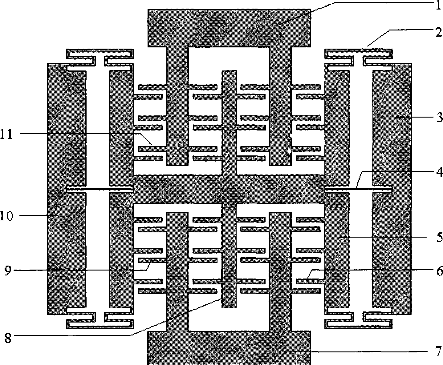
[0031] Embodiment 1: When there is an upward acceleration acting on the acceleration sensor, under the action of inertial force, the movable electrode 6 connected to the mass block will have a downward direction relative to the fixed electrode 11 and the fixed electrode 9 connected to the bonding block. At this time, the capacitance C1 formed between the movable electrode 6 and the upper fixed electrode 11 will become smaller, while the capacitance C2 formed between the movable electrode 6 and the lower fixed electrode 9 will become larger. The magnitude of the acceleration can be measured by differential detection of the variation of C2.

Embodiment 2

[0032] Embodiment 2: When there is a leftward acceleration acting on the acceleration sensor, under the action of inertial force, the movable electrode 6 connected to the mass block will have a direction to the fixed electrode 11 and fixed electrode 9 connected to the bonding block. At this time, the capacitance C3 formed between the movable electrode 6 and the upper fixed electrode 11 will not change, and the capacitance C4 formed between the lower fixed electrode 9 will also remain unchanged, so that the movable electrode 6 and the upper and lower The total capacitance formed between the fixed electrode 11 and the fixed electrode 9 will also remain unchanged. In this way, lateral acceleration will not change the output of the sensor, that is, there will be no lateral sensitivity interference during operation.

Embodiment 3

[0033] Embodiment 3: Due to the deviation of the process, the structure is mismatched, and the left and right comb teeth are asymmetrical. When a lateral acceleration acts on the acceleration sensor, as described in Embodiment 2, lateral sensitivity interference will occur. However, due to the effect of the anti-interference beam 4, the displacement of the mass block 5 and the movable electrode 6 connected thereto is greatly limited, and no transverse sensitivity interference will occur.


PUM


Abstract

The invention provides a six-beam acceleration transducer and a preparation method thereof. The acceleration transducer comprises a mass block which is connected on a left-right bonding block by an elastic beam and provided with moving electrodes, and an upper fixed electrode and a lower fixed electrode which are connected with an up-down bonding block and positioned on the mass block; the elastic beam comprises a conduplicate beam and an anti-interference beam; the upper fixed electrode is independent from the lower fixed electrode, the moving electrodes are connected together by the mass block, a pair of differential capacitors are formed by the upper fixed electrode and the lower fixed electrode and the moving electrodes; the values of the two differential capacitors are inversely proportional to the change trend of an applied acceleration in operation; and the left-right bonding block and the up-down bonding block connected by the fixed electrodes are fixed on a glass substrate by electrostatic bonding. The acceleration transducer has the advantages of small size, great static capacitance, strong anti-interference capacity, no horizontal (non-sensitive) interference, high sensitivity, simple structure, flexible design, easy machining and the like.

Description

(1) Technical field [0001] The invention relates to a sensor structure, in particular to a new six-beam structure acceleration sensor with large capacitance differential capacitive ability and strong anti-interference ability. (2) Background technology [0002] Micro-mechanical inertial instruments based on micro-electro-mechanical systems (MEMS) have been widely used and developed rapidly due to their small size, low cost, simple structure, and compatibility with integrated circuits. [0003] With the continuous development of acceleration sensors, people have higher and higher requirements for the sensitivity and precision of micro-acceleration sensors. For sensors made of traditional rectangular mass blocks, the mass of the detection mass is generally relatively small, and the detection capacitance formed by this structure is distributed on both sides of the mass block, which is generally not very large, which is not conducive to increasing the sensitivity of the sensor. ...

Claims


Application Information

Patent Timeline
IPC IPC(8): G01P15/125B81B7/02B81B3/00B81C1/00
Inventor 陈伟平刘晓为陈晓亮郭玉刚
Owner HARBIN INST OF TECH
Why Eureka
Try Eureka