Electrode assembly, electric arc tube special for ceramic method halide lamp, and manufacturing method thereof

A technology of halide lamps and ceramic metals, which is applied in the manufacture of electrode systems, cold cathodes, and discharge tubes/lamps, etc. It can solve the problems of ceramic tailpipe bursting, reduced ignition reliability, and failure to cover ceramic tube bursts, etc. , to achieve the effect of prolonging the service life and improving the operability

Active Publication Date: 2009-06-17
浙江新光阳照明股份有限公司
View PDF0 Cites 5 Cited by
  • Summary
  • Abstract
  • Description
  • Claims
  • Application Information

AI Technical Summary

Problems solved by technology

When sealing, the glass solder should first cover enough length of the electrode area to prevent the halide from corroding the metal rod, and at the same time not cover too much molybdenum ring to prevent the bursting of the ceramic tube in this area, which makes the vacuum seal The length of the zone must be kept within a small error range in each lamp, otherwise the ignition reliability of the ceramic metal halide lamp will be greatly reduced, and it is easy to cause the bursting of the ceramic tailpipe

Method used


Image

  • Electrode assembly, electric arc tube special for ceramic method halide lamp, and manufacturing method thereof
  • Electrode assembly, electric arc tube special for ceramic method halide lamp, and manufacturing method thereof
  • Electrode assembly, electric arc tube special for ceramic method halide lamp, and manufacturing method thereof

Examples


Embodiment 1

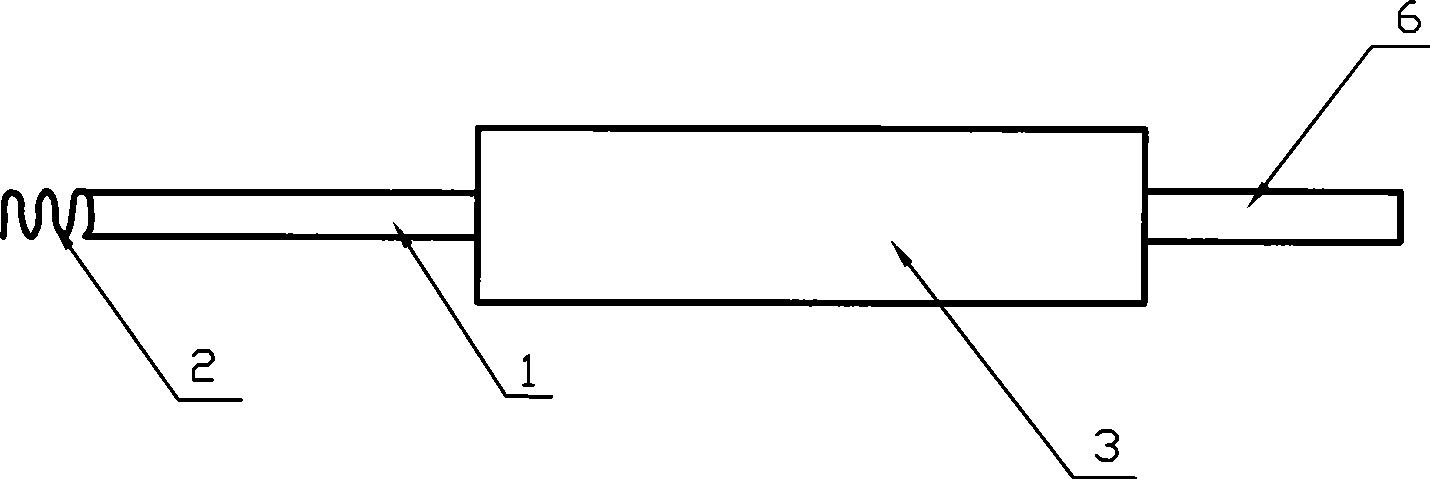
[0020] Embodiment 1: as figure 1 As shown, it is a structural schematic diagram of an embodiment of a special electrode assembly, including a tungsten electrode rod 1, a tungsten ring 2, a cermet rod 3, and a metal rod 6. The material of the cermet rod 3 is composed of alumina and molybdenum. The tungsten ring 2, the tungsten electrode rod 1, the cermet rod 3 and the metal rod 6 are respectively coaxially welded in sequence to form the whole electrode structure.

Embodiment 2

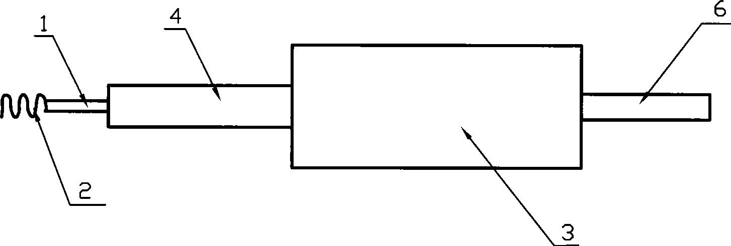
[0021] Embodiment 2: as figure 2 As shown, it is a structural schematic diagram of another embodiment of the special electrode assembly, including a tungsten electrode rod 1, a tungsten ring 2, a cermet rod 3, a tungsten rod 4, and a metal rod 6. The material of the cermet rod 3 is made of alumina and Molybdenum composition. The tungsten ring 2, the tungsten electrode rod 1, the tungsten rod 4, the cermet rod 3 and the metal rod 6 are respectively coaxially welded in sequence to form the whole electrode structure.

Embodiment 3

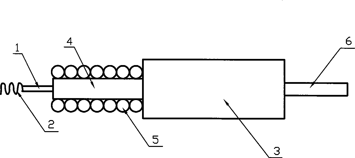
[0022] Embodiment 3: as image 3 As shown, it is a structural schematic diagram of another embodiment of the special electrode assembly, including tungsten electrode rod 1, tungsten ring 2, cermet rod 3, tungsten rod 4, molybdenum ring 5, metal rod 6, and the material of cermet rod 3 Composed of alumina and molybdenum. The molybdenum ring 5 is wound on the tungsten rod 4, and the tungsten ring 2, the tungsten electrode rod 1, the tungsten rod 4 equipped with the molybdenum ring 5, the cermet rod 3 and the metal rod 6 are respectively coaxially welded to form the whole electrode structure.


PUM


Abstract

The invention discloses a special electrode component and an electric arc tube of a ceramic metal halide lamp and a manufacturing method of the electric arc tube, the special electrode component comprises a metal ceramic rod, one end of the metal ceramic rod is connected with a tungsten electrode rod, the other end is connected with a niobium rod utilized to feed, besides, the metal ceramic rod, the tungsten electrode rod and the niobium rod are in an identical axial line, and the end portion of the tungsten electrode rod is a tungsten ring. At least one special electrode component is used in the electric arc tube, and the electric arc tube is utilized to manufacture the ceramic metal halide lamp, when in seal production, glass solder is only required to cover a portion or all parts of the metal ceramic rod of the special electrode component. The invention utilizes novel materials in the special electrode component, is greatly simple and convenient in technique for sealing tail tubes of a ceramic discharge chamber, is strong in operation reliability, reduces crack problems in seal positions of the ceramic tail tubes, and prolongs the service life of finished lamps.

Description

technical field [0001] The invention relates to a ceramic metal halide lamp and a manufacturing method thereof, in particular to a special electrode assembly for a ceramic metal halide lamp, an arc tube and a manufacturing method thereof. Background technique [0002] At present, the commonly used electrode assembly is coaxially welded by a niobium rod—a molybdenum rod with a molybdenum ring or a niobium rod—a tungsten rod with a molybdenum ring and a tungsten electrode head. The conventional sealing method is to weld the used niobium rod with the molybdenum rod or tungsten rod with molybdenum ring, and then use glass solder to realize vacuum sealing between them and the tail pipe of the ceramic discharge chamber. When sealing, the glass solder should first cover enough length of the electrode area to prevent halides from corroding the metal rod, and at the same time not cover too much molybdenum ring to prevent the bursting of the ceramic tube in this area, which makes the ...

Claims


Application Information

Patent Timeline
Patent Type & Authority Applications(China)
IPC IPC(8): H01J61/073H01J9/00
Inventor 翟建跃诸定昌雅各布·马耶
Owner 浙江新光阳照明股份有限公司
Why Eureka
Try Eureka