Automatic ice melting method for multiple division electricity transmission line and special switch thereof

A transmission line and ice-melting method technology, which is applied to the installation of electrical components and cables, overhead installation, etc., can solve the problems of high cost, loss of load, high-power multi-split transmission line ice melting, etc., to reduce labor intensity and improve safety effect

Inactive Publication Date: 2009-06-17
何彪
View PDF0 Cites 36 Cited by
  • Summary
  • Abstract
  • Description
  • Claims
  • Application Information

AI Technical Summary

Problems solved by technology

[0005] 2. Composite conductor method: This method is expensive and limited by conditions, so it is not suitable for multi-split transmission lines
[0006] 3. Manual knocking method: only suitable for low-voltage distribution lines
[0007] 4. Direct current method: This method solves the problem of power failure and series connection of multi-circuit

Method used


Image

  • Automatic ice melting method for multiple division electricity transmission line and special switch thereof
  • Automatic ice melting method for multiple division electricity transmission line and special switch thereof
  • Automatic ice melting method for multiple division electricity transmission line and special switch thereof

Examples

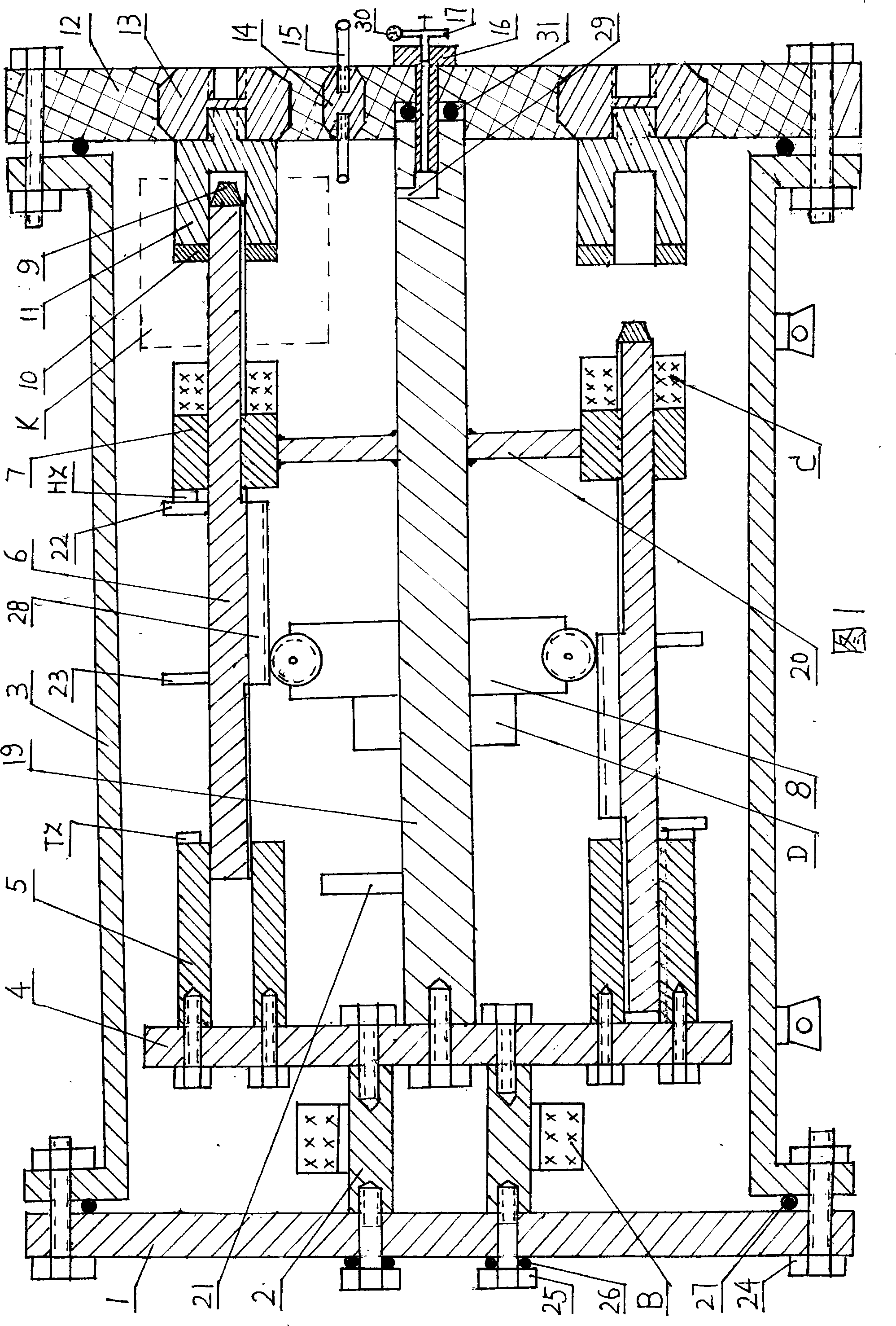

Embodiment 1

[0026] Embodiment 1 Manual remote control automatic ice melting method

[0027] The ice-melting method of this embodiment is the same as the above-mentioned technical solution, and will not be repeated here. The structure and working principle of the special switch will be introduced in detail below.

[0028] As shown in Figure 1, the drainage flange 1 and the insulating end cover 12 are respectively fixed on the flanges at both ends of the metal casing 3 through O-rings 27 and flange bolts 24, and one end of the square central column 19 is passed through an O-ring 31 And the inflation screw 16 is fixed on the insulating end cover 12, the three-way valve 17 is installed on the central hole of the inflation screw 16, and an outlet of the three-way valve 17 is equipped with a barometer 30, and the other outlet is an inflation and deflation interface, and the square center column 19 There is an air hole 29 at the end that communicates with the central hole of the inflation screw ...

Embodiment 2

[0032] Embodiment 2 Automatic ice melting method controlled by frost sensor signal

[0033] This embodiment is basically the same as Example 1, except that frost sensors and sub-conductor current source transformers for supplying power are respectively installed on the sub-conductors in the ice-melting section.

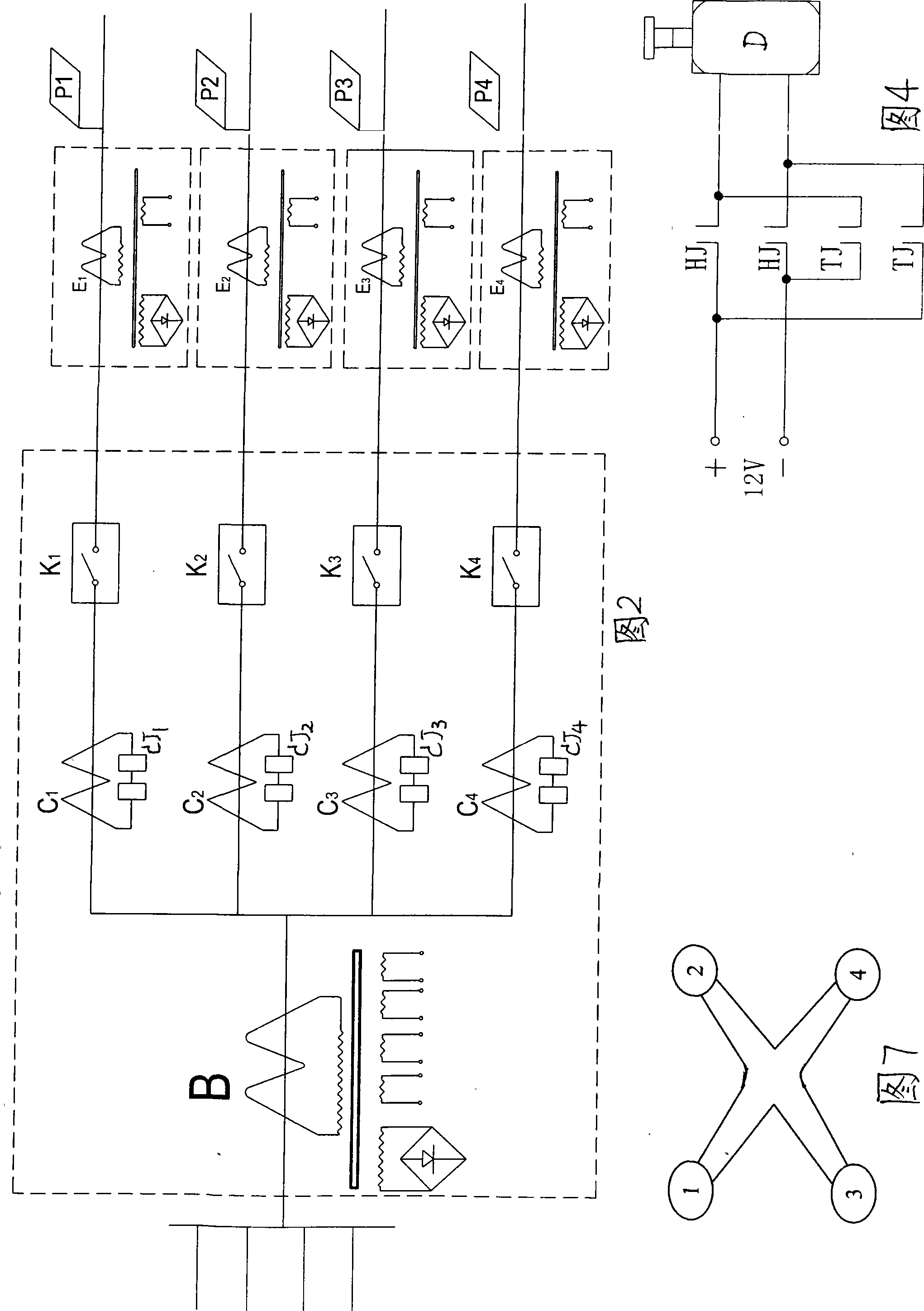
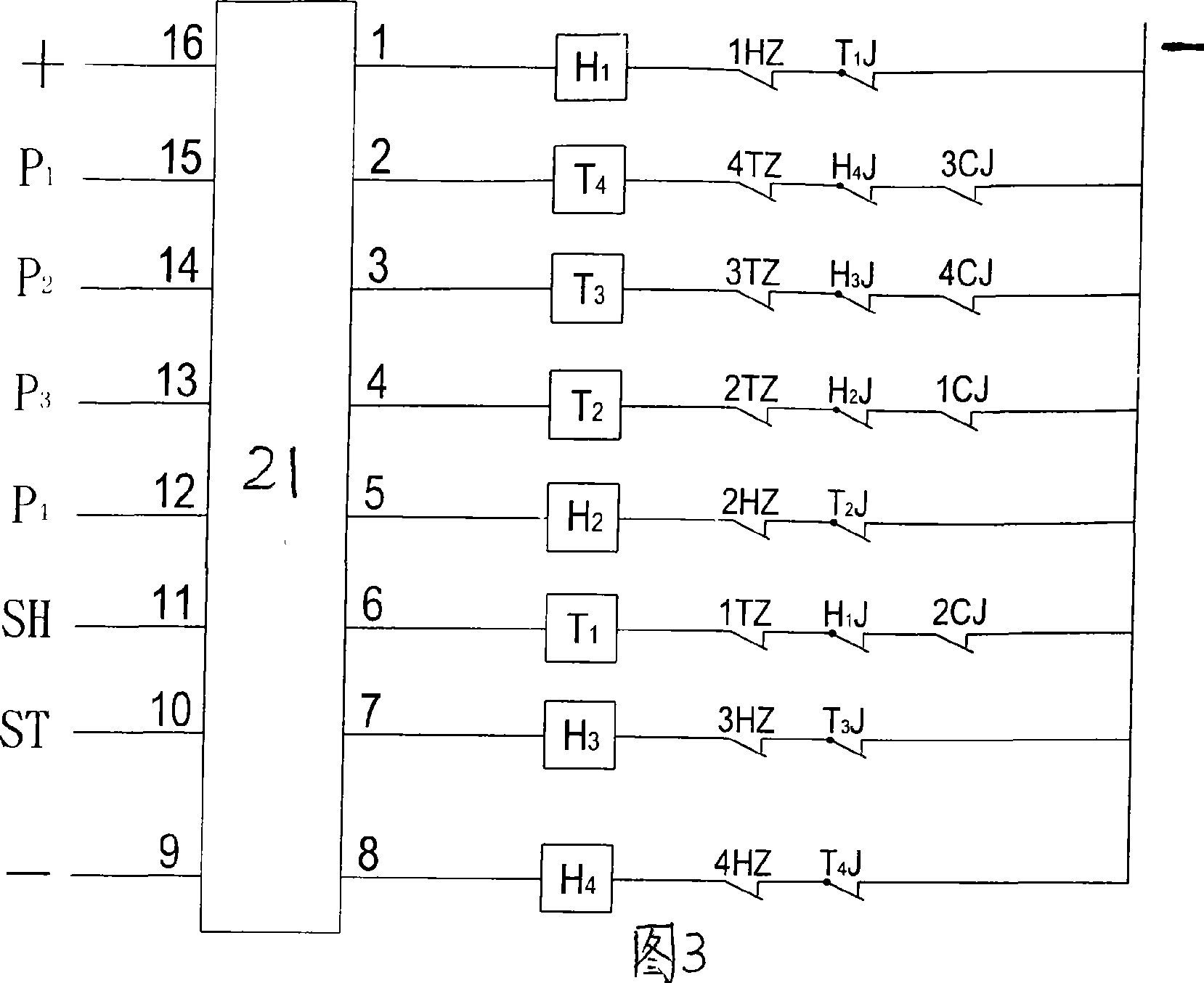
[0034]The automatic control principle and circuit principle are shown in Figure 2-6. When the line is covered with ice above 5mm, the resonator in the frost sensor vibrates and sends out a pulse-type ice-melting signal, which is transmitted to the computer automatic control device in the special switch through the sub-wire, and the computer chip melts the ice according to the program.

[0035] For example, the sub-conductor numbers of the four-split transmission line are shown in Figure 7, and the ice-melting action procedure is as follows:

[0036] (1) Confirm all sub-wire combination switches K 1 -K 4 They are all in the closed state, and start to melt the ice on...


PUM


Abstract

Disclosed are an automatic deicing method for multiple bundle power transmission lines and a special switch thereof. The technical scheme includes firstly mutually separating and insulating sub-wires on needed multiple bundle power transmission line sections, mounting the special switch at the end portion of one section of a pole tower, wherein the special switch is internally equipped with movable-static contact combined switches with conductor number equal to the amount of the sub-wires, then sending orders via a remote controller, namely, on the premise of maintaining the movable-static contact combined switches of one or two to-be-deiced sub-wires conducted, starting a driving motor to switch off the movable-static contact combined switches of other sub-wires, then applying running load current of the power transmission line to the sub-wires to be deiced so as to increase current density of the sub-wires for heating and deicing, and further, sequentially deicing other sub-wires according to the method. The automatic deicing method has the advantages of automatic deicing without cutting off the power, which utilizes load current to deice, thereby avoiding power transmission load loss and electric switching operation, reducing labor intensity of workers and increasing safety of deicing operation.

Description

technical field [0001] A method and equipment for preventing ice and snow disasters on a high-voltage, high-power transmission line. Background technique [0002] With the unreasonable increase of power generation capacity and the increasing expansion of the power grid, more and more high-power, high-voltage, cross-regional long-distance transmission lines pass through low-temperature, high-humidity and freezing areas. Many countries and regions around the world have multiple Power grid disintegration and large-scale power outages occurred due to severe icing of transmission lines. The ice and snow disaster in January 2008 caused large-scale tower collapses and power cuts in the power grid lines in central and southern China, causing direct economic losses of more than 100 billion yuan. The cause of the accident was that the low-temperature and high-humidity weather environment formed thick and heavy ice on the transmission wires, and the gravity of the ice broke the wires,...

Claims


Application Information

Patent Timeline
IPC IPC(8): H02G7/16
Inventor 何彪
Owner 何彪
Why Eureka
Try Eureka