Vent gas circulating type spiral pipe blast drier and its drying method

A spiral airflow and airflow drying technology, which is applied in drying solid materials, heating to dry solid materials, drying, etc., can solve the problems of installation, maintenance, cleaning difficulties, installation, maintenance and cleaning difficulties, and air flow dryers. , to achieve the effect of shortened drying time, compact structure and easy construction

Inactive Publication Date: 2009-06-24
张文华
View PDF0 Cites 11 Cited by
  • Summary
  • Abstract
  • Description
  • Claims
  • Application Information

AI Technical Summary

Problems solved by technology

But it also has some defects: it takes up a lot of space, and if it is placed indoors, the required factory building height is very high, so most manufacturers protrude the drying pipe from the roof, which causes difficulties in installation, maintenance and cleaning. Airflow dryers are diffi...

Method used


Image

  • Vent gas circulating type spiral pipe blast drier and its drying method
  • Vent gas circulating type spiral pipe blast drier and its drying method

Examples


Embodiment Construction

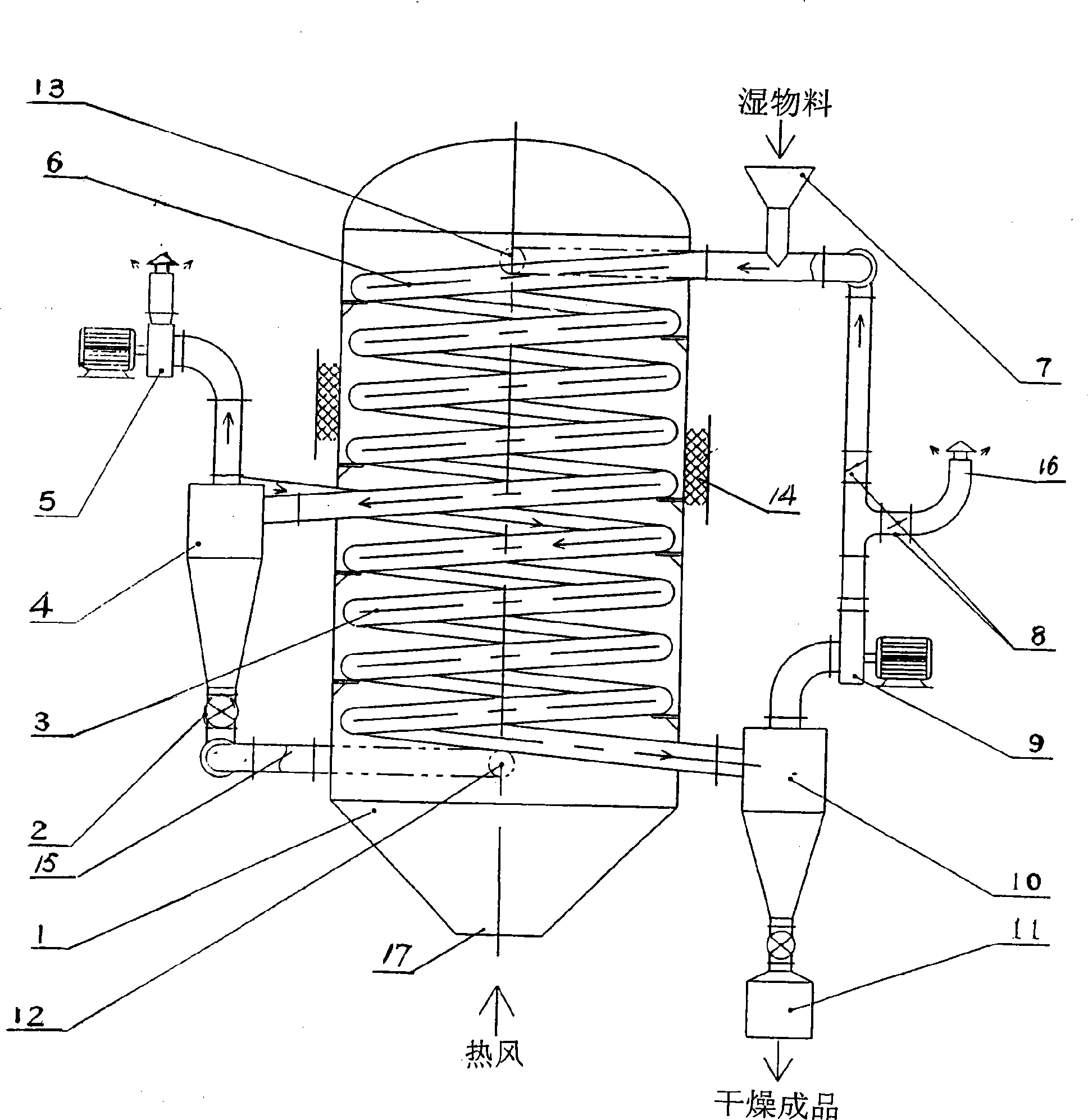
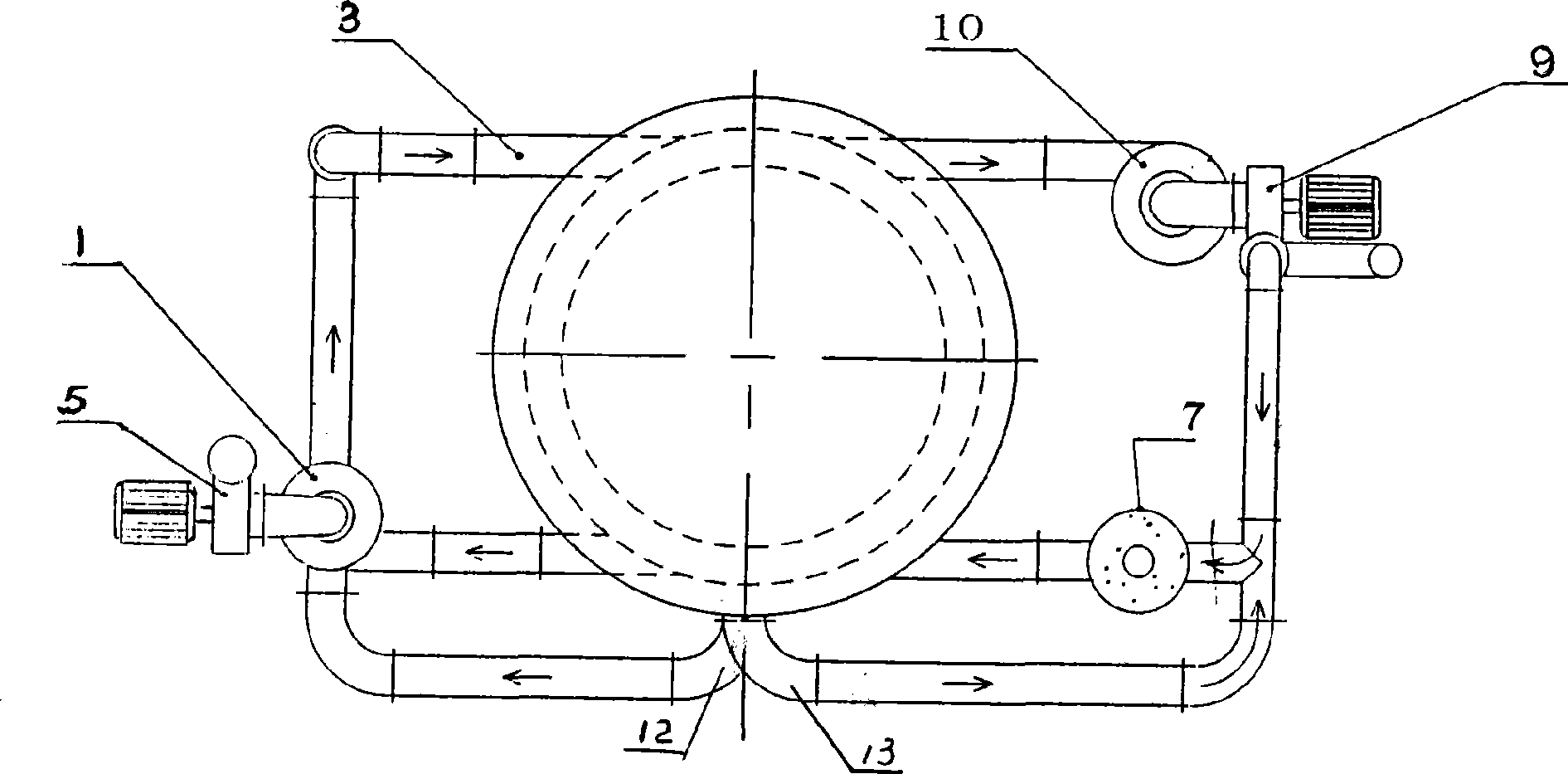
[0034] Refer to attached figure 1 , 2 , Exhaust gas circulating spiral tube air dryer includes cylindrical container 1, shut-off fan 2, primary spiral air drying tube 6, secondary spiral air drying tube 3, primary drying cyclone separator 4, feeding device 7, secondary air drying tube Drying cyclone separator 10, primary drying induced draft fan 5, secondary drying induced draft fan 9 and receiving hopper 11.

[0035] Inside the cylindrical container 1 is provided with a primary spiral airflow drying pipe 6 and a secondary spiral airflow drying pipe 3, a hot air inlet 17 is provided at the bottom of the cylindrical container, and a second hot air outlet 13 is provided at the upper part of the cylindrical container , the bottom of the cylindrical container is provided with a first hot air outlet 12; the second hot air outlet 13 of the upper part of the cylindrical container is connected to the secondary drying cyclone separator 9, the feeder 7 and the primary spiral airflow dr...


PUM


Abstract

The invention relates to an exhaust gas circulating spiral pipe pneumatic dryer and a drying method thereof. A pneumatic drying pipe is made into the spiral pneumatic drying pipe, thereby leading the spiral pneumatic drying pipe to be positioned in a high temperature zone and forming the convection heat transfer in the pipe and the conduction heat transfer out of the pipe, namely the heating of the interior and the exterior of materials is simultaneously carried out, thereby being capable of improving the heat transfer rate and shortening the drying time of the materials. The exhaust gas circulation is further adopted for heating the materials and fully utilizing waste heat in the exhaust gas. The structure comprises a cylindrical container, a first-stage spiral pneumatic drying pipe, a second-stage spiral pneumatic drying pipe, a first-stage drying cyclone separator, a second-stage drying cyclone separator, a first-stage drying induced draft fan, a second-stage induced draft fan and a receiving hopper; the first-stage spiral pneumatic drying pipe and the second-stage spiral pneumatic drying pipe are arranged in the cylindrical container, a hot air inlet is formed at the bottom part of the cylindrical container, a second hot air outlet is formed at the upper part of the cylindrical container, and a first hot air outlet is formed at the lower part of the cylindrical container.

Description

technical field [0001] The invention relates to a tail gas circulation type spiral tube airflow dryer and its drying method. The airflow drying pipe is made into a spiral airflow drying pipe, so that the spiral airflow drying pipe is located in a high temperature zone, forming a convective heat transfer inside the pipe. The outside of the tube is conduction heat transfer, that is, the material is heated inside and outside at the same time, which can increase the heat transfer rate and shorten the drying time of the material; and use part of the exhaust gas circulation to heat the material to make full use of the waste heat in the exhaust gas to achieve the purpose of energy saving. Background technique [0002] The airflow dryer has been widely used in chemical, pharmaceutical, food, dyestuff, plastic and other industrial production, because the airflow dryer has many advantages: high drying strength, short drying time, large processing capacity, simple equipment, convenient ...

Claims


Application Information

Patent Timeline
IPC IPC(8): F26B17/10F26B3/22F26B3/02
Inventor 张文华赵厚林
Owner 张文华
Why Eureka
Try Eureka