LED optical strip and method of manufacturing the same

A technology for light-emitting diodes and a manufacturing method, which is applied in the fields of semiconductor/solid-state device manufacturing, electrical components, and electric-solid-state devices, etc., can solve the problems of increased cost, increased weight and size of light-emitting diode light bars, complicated manufacturing process procedures, etc. The effect of process cost

Inactive Publication Date: 2009-06-24
EVERLIGHT ELECTRONICS
View PDF0 Cites 6 Cited by
  • Summary
  • Abstract
  • Description
  • Claims
  • Application Information

AI Technical Summary

Problems solved by technology

[0003] However, such a process requires multiple sealing procedures, which makes the production process too complicated
Moreover, due to the complexity of the production pr

Method used


Image

  • LED optical strip and method of manufacturing the same
  • LED optical strip and method of manufacturing the same
  • LED optical strip and method of manufacturing the same

Examples


Example Embodiment

[0020] Implementation

[0021] The invention discloses a light-emitting diode light bar and a manufacturing method thereof. In order to make the description of the present invention more detailed and complete, please refer to the following description and cooperate with it Figure 1 to Figure 6 .

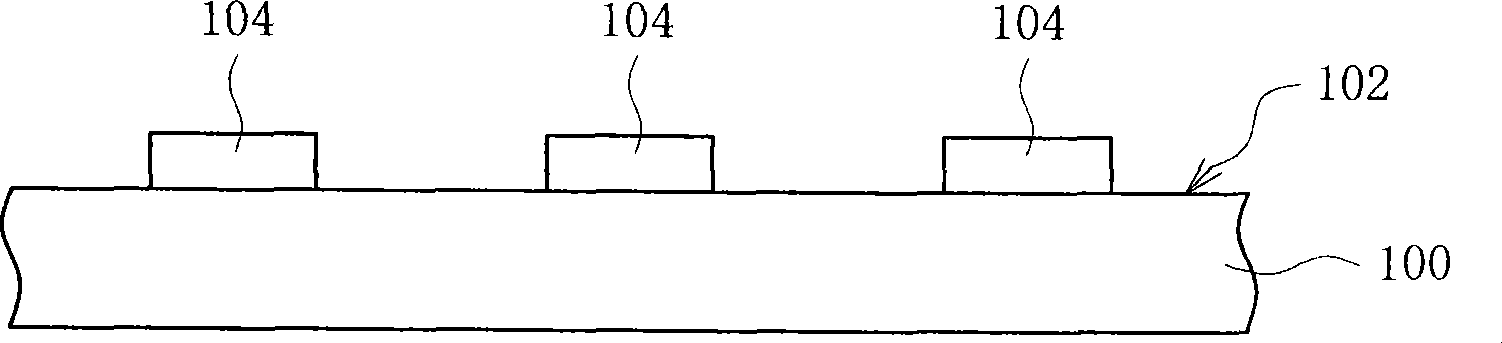
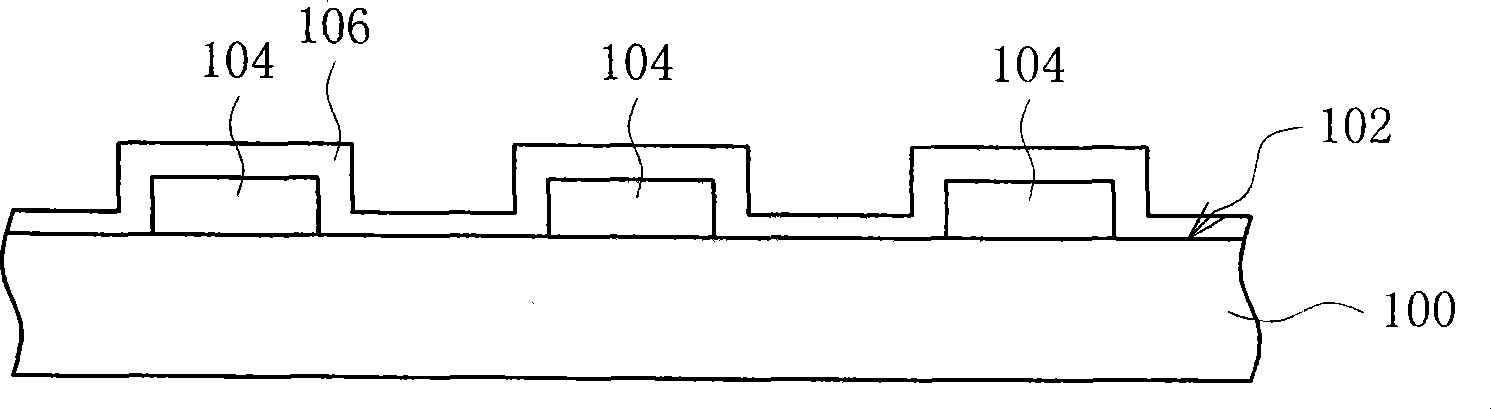
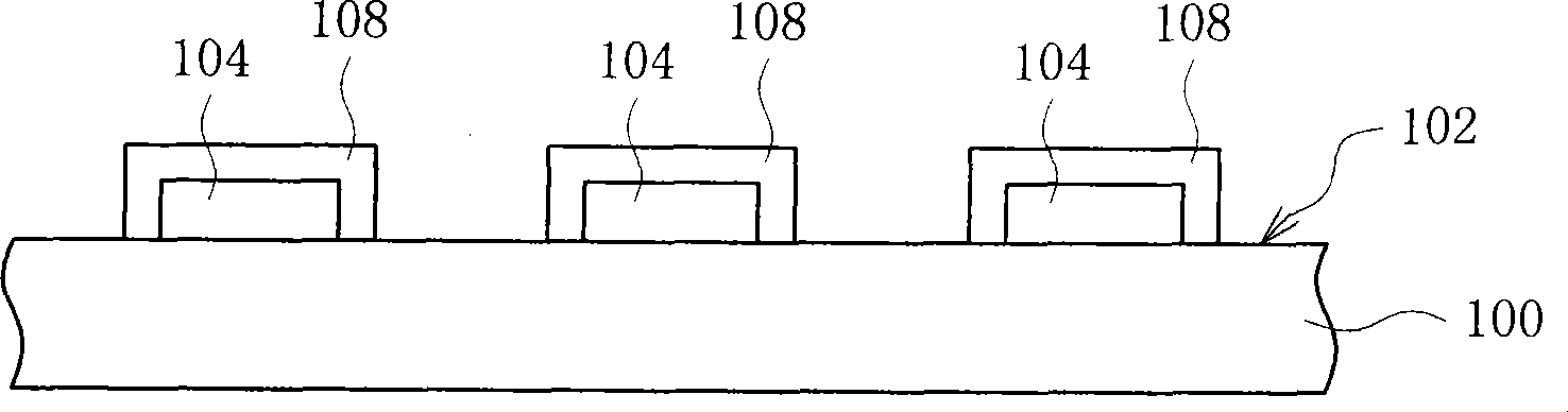
[0022] Please refer to Figure 1 to Figure 6 , Which is a schematic diagram of the manufacturing process of a light-emitting diode light bar according to a preferred embodiment of the present invention, wherein Figure 1 to Figure 4 Is a schematic cross section, Figure 5 versus Figure 6 It is a schematic diagram of the top view. In an exemplary embodiment, fabricated as Figure 6 When the light-emitting diode light bar 112 is shown, the circuit board 100 can be provided first for chips to be arranged on it, and the circuit board 100 is preferably pre-installed with the required circuit layout. In one embodiment, the circuit board 100 can be a general printed circuit board. Next, using...


PUM


Abstract

The invention discloses an LED light bar and a manufacturing method thereof; the LED light bar at least comprises a circuit board, a plurality of LED chips arranged on one surface of the circuit board and electrically connected with the circuit board, a plurality of sealing colloids respectively covering the LED chips, as well as a plurality of reflected colloids respectively enwrapping the lateral sides of the sealing colloids.

Description

technical field [0001] The invention relates to a light-emitting component and a manufacturing method thereof, in particular to an LED light bar (LED Light Bar) and a manufacturing method thereof. Background technique [0002] At present, when making LED light strips, the LED chip is firstly placed on the package holder, wherein the package holder is preset with a protruding reflective cover, and the LED chip is located in the inner area surrounded by the reflective cover. Generally speaking, the protruding reflective cover on the package holder is injection molded at the same time when the package holder is manufactured. Lead wire welding is then performed, followed by encapsulation to form an encapsulant covering the LED chip and wires, and filling the gap between the reflective cover and the LED chip to form the LED assembly. Next, the light-emitting diode assembly is disposed on a preset position on the printed circuit board by using surface mount technology (Surface Mo...

Claims


Application Information

Patent Timeline
IPC IPC(8): H01L21/50H01L25/00H01L25/075
Inventor 林荣泉谢忠全
Owner EVERLIGHT ELECTRONICS
Why Eureka
Try Eureka