Fixing structure of thermostat

A technology of installation structure and thermostat, which is applied in the direction of instrumentation, temperature control, engine cooling, etc., can solve problems such as troublesome operation, damage to the sealing of the joint between the engine main body and the outlet shell, and achieve good operability and simplified insertion the effect of the job

Inactive Publication Date: 2009-06-24
UCHIYAMA MFG
View PDF2 Cites 5 Cited by
  • Summary
  • Abstract
  • Description
  • Claims
  • Application Information

AI Technical Summary

Problems solved by technology

However, when assembling the components in the inlet housing, it is necessary to install and fix the return spring between the inlet housing and the frame of the thermostat in an elastically biased state, but this work is extremely difficult and cumbersome.
[0008] In addition, it is expected that these thermostats are fixed in the outlet housing or the inlet housing without play, and when the outlet housing or the inlet housing is connected and fixed to the engine main body, there are differences between the two based on design tolerances and the like. In the case of misalignment, etc., it is difficult for the thermostat to follow the misalignment. Therefore, stress is generated on each part due to the connection, which hinders the correct opening and closing of the valve, or damages the junction between the engine body and the outlet housing or inlet housing. tightness

Method used


Image

  • Fixing structure of thermostat
  • Fixing structure of thermostat
  • Fixing structure of thermostat

Examples


Embodiment 1

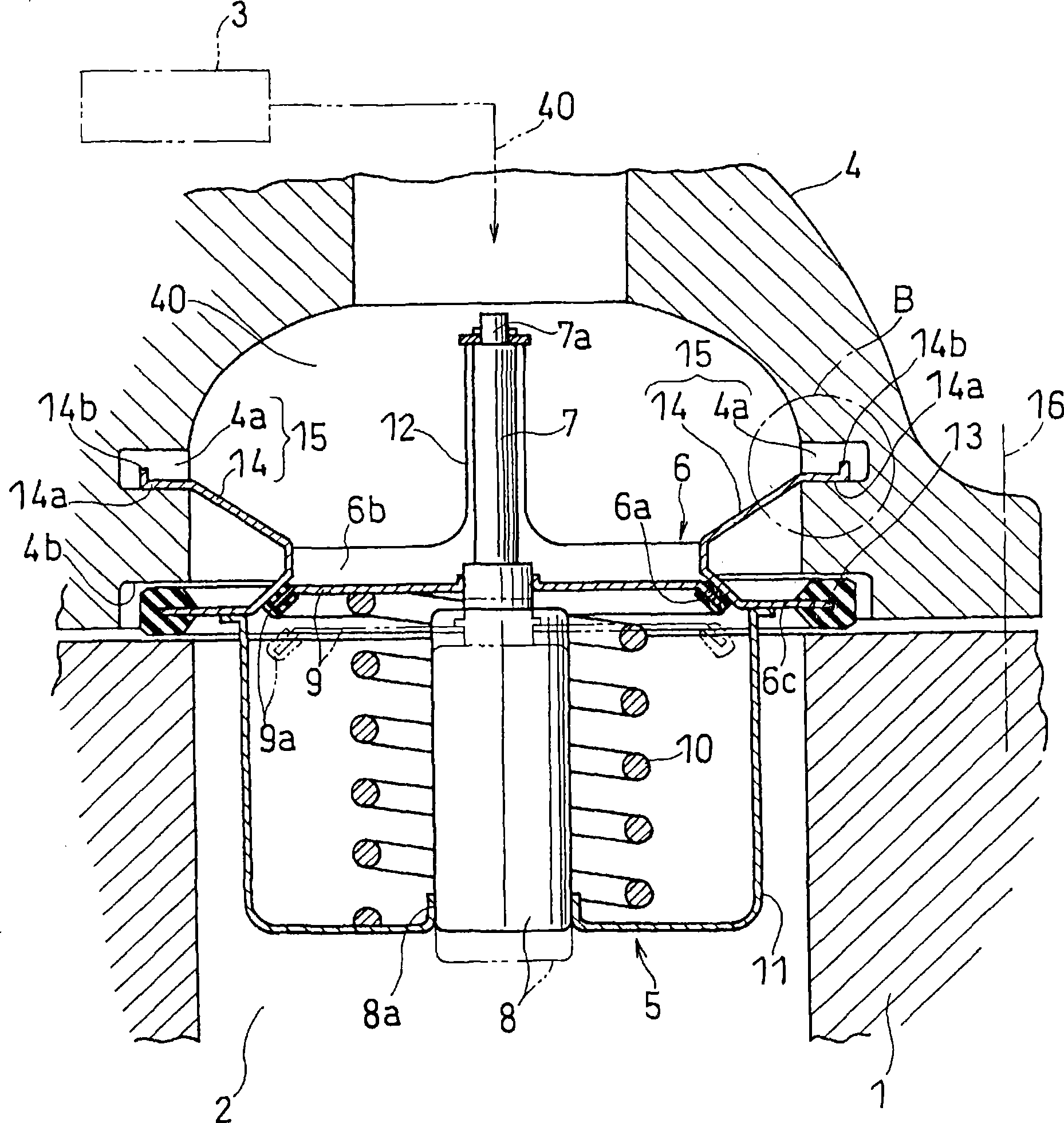
[0061] figure 1 An example of the mounting structure of the thermostat to which the present invention is applied when the internal combustion engine is a water-cooled engine is shown. In the figure, the thermostat 5 is located between the cooling water circulation path 40 and the cooling water flow path 2 of the engine body 1, and the thermostat 5 is used to control the cooling water cooled by heat radiation in the radiator (radiating mechanism) 3. , flows into the cooling water flow path (cooling medium flow path) 2 through the inlet casing 4 constituting a part of the cooling water circulation path (cooling medium circulation path) 40, and the cooling water flow path 2 leads to the engine main body (cylinder head portion) which is the main body of the internal combustion engine. ) 1 water cooling jacket (not shown).

[0062] The thermostat 5 has: an annular support base 6, the inner peripheral portion of which is a valve seat 6a; a valve casing 8, which is provided with a c...

Embodiment 2

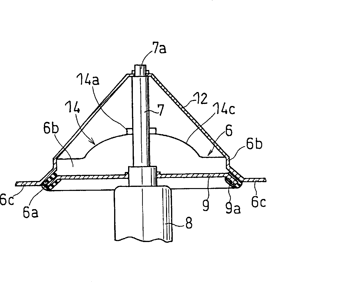
[0075] Figure 5 Referring to the second embodiment, the locking tongue 14A constituting the locking mechanism 15 is produced separately from the support base 6 and integrally joined to the flange portion 6 c of the support base 6 . The front side portion 14Aa of the locking tongue piece 14A is bent in the diameter-expanding direction, and the base portion of the locking tongue piece 14A is integrally bonded to the flange portion 6c. This is done by adhesives, riveting, screwing or the like. The illustration shows the joint integration by riveting. In the case of this embodiment, unlike the locking tongue 14 formed by cutting from the support base 6 as in the above-mentioned first embodiment, there is an advantage that there are few restrictions on the formation position of the locking tongue 14A. The other configurations are the same as above, and thus the same reference numerals are assigned to the same parts and their descriptions are omitted.

Embodiment 3

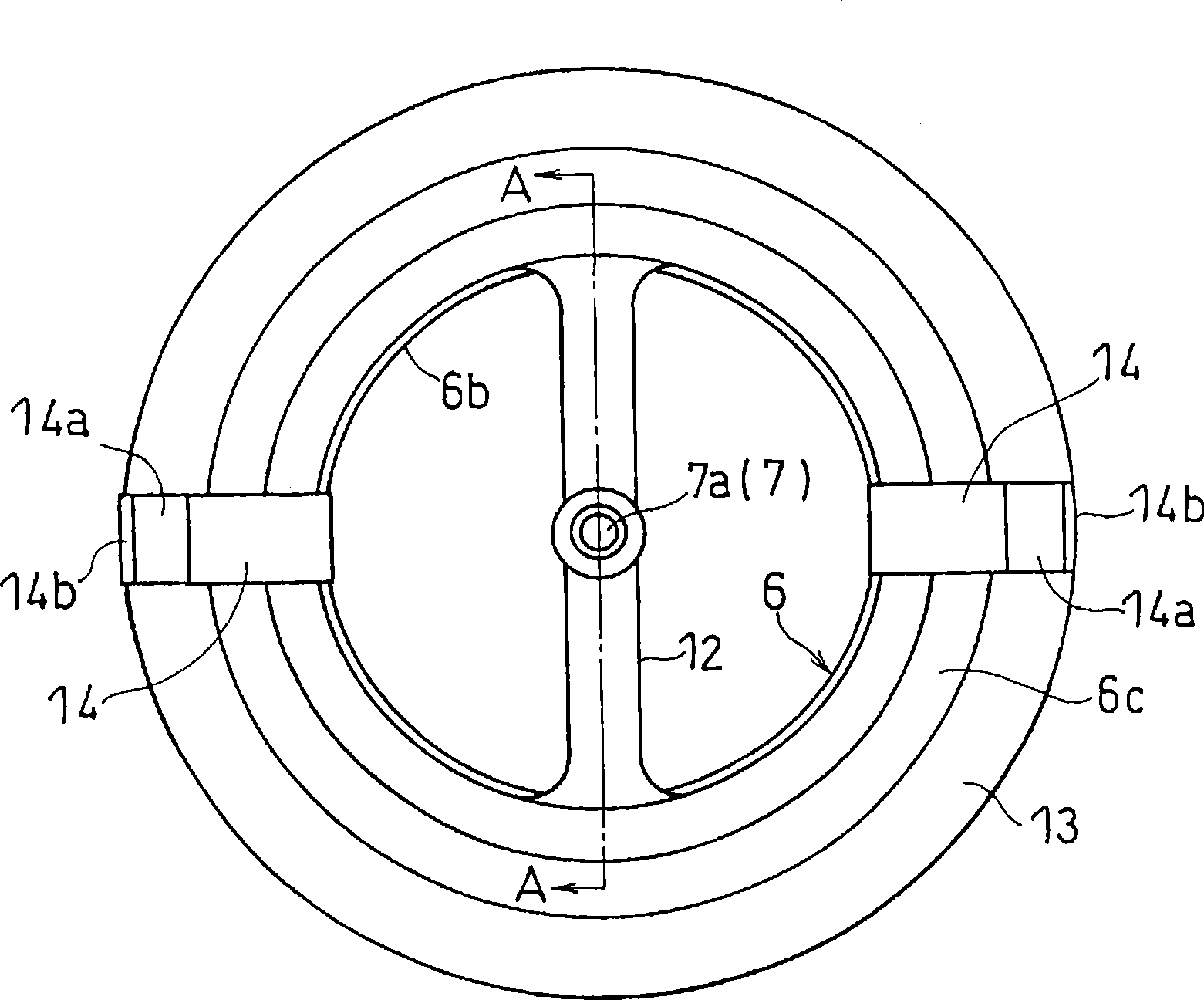
[0077] Figure 6 shows the third embodiment, Figure 7 (a), (b), and (c) show modifications thereof. The thermostat locking mechanism 15 of this embodiment has: at least one pair of locking tongue pieces 14C, and a rising portion (becoming a part of the vertical portion 6b connected to the inner diameter side of the valve seat 6a) 14Ca standing up from the support base 6 And its front side part is constituted by a bent reed part 14Cb; the locking step part 4c is formed on the inner wall surface of the cooling water circulation path 40 of the inlet housing 4, and is elastically connected with the reed part 14Cb of the locking tongue 14C The thermostat 5 can be elastically installed and supported.

[0078] Figure 6 The illustrated locking tongue 14C is formed by cutting from a 180-degree facing position of the support base 6 (a position perpendicular to the restriction frame 12 ), and the spring part 14Cb is curved in a radially expanding direction to form a "U" shape. The ...


PUM


Abstract

A fixing structure of a thermostat in which a thermostat can be built stably in the circulation path of cooling medium, and the circulation path of cooling medium can be fastened and fixed to the body of an internal combustion engine without causing damage to the function of the thermostat. The thermostat (5) comprises a frame (12) formed integrally with an annular supporting substrate (6) having the inner circumferential edge portion serving as a valve seat (6a) and regulating the projecting head portion (7a) of a telescopic rod (7). The fixing structure is characterized in that a latching means (15) is provided between the supporting substrate (6) and the inner wall portion of the circulation path (40) of cooling medium, and, after the thermostat (5) is latched at a predetermined position in the circulation path (40) of cooling medium by the latching means (15), the circulation path (40) of cooling medium and the body (1) of internal combustion engine are fastened integrally with a gasket (13) interposed between them, thus fixing the thermostat (5) at a predetermined position between the circulation path (40) of cooling medium and the cooling medium channel (2) of the body (1) of internal combustion engine.

Description

technical field [0001] The invention relates to an installation structure of a thermostat. The installation structure of the thermostat is located between the cooling medium flow path in the internal combustion engine and the cooling medium circulation path for cooling and circulating the cooling medium in order to cool the internal combustion engine, and the cooling medium Flow control of a cooling medium between a circulation path and a cooling medium flow path of an internal combustion engine. Background technique [0002] In order to control the temperature of the cooling water flowing back in the water cooling jacket (cooling water path) of the internal combustion engine, at the connection part of the inlet housing (inlet housing) or outlet housing (outlet housing) connected between the cooling water path of the engine body and the radiator With thermostat. The thermostat operates a valve according to the temperature of the cooling water in the cooling water passage, a...

Claims


Application Information

Patent Timeline
Patent Type & Authority Applications(China)
IPC IPC(8): F01P7/16
CPCF01P2070/00G05D23/022F01P7/16Y10T29/53552
Inventor 高谷佳浩
Owner UCHIYAMA MFG
Why Eureka
Try Eureka