
Tenon joint type spatial mesh structure

A space grid, tenon-joint technology, applied in underwater structures, infrastructure engineering, water conservancy projects, etc., can solve the problems of inability to apply a large number of space frame structures, high construction difficulty, protracted time, etc., to achieve water conservation auxiliary facilities, Simple and fast construction, reducing the effect of auxiliary facilities

Inactive Publication Date: 2009-07-01
黎彪钦
View PDF3 Cites 4 Cited by
  • Summary
  • Abstract
  • Description
  • Claims
  • Application Information

AI Technical Summary

Problems solved by technology

[0002] Nowadays, there are few cases where "space frame structure" is used in civil engineering retaining walls, embankments, and waterway structures. We know that there are probably gravity structures in which precast concrete lattice bars are stacked in a criss-cross manner, and the hollow parts are filled. Gravel grading is also used for soil retaining and drainage. In addition, wood is used to complete the grid structure in the same way. The rest is probably only the grid structure used for embankment slopes. The reason why space frame structures cannot be widely used in this type of project , mainly in the problems of material, node combination and construction method
For example, in the previously used space frame structure, the combination of its nodes is one of the main points of the space frame structure. However, the existing combination of nodes between two components is too complicated, which is not only difficult to construct, but also protracted.

Method used


Image

  • Tenon joint type spatial mesh structure
  • Tenon joint type spatial mesh structure
  • Tenon joint type spatial mesh structure

Examples


Embodiment Construction

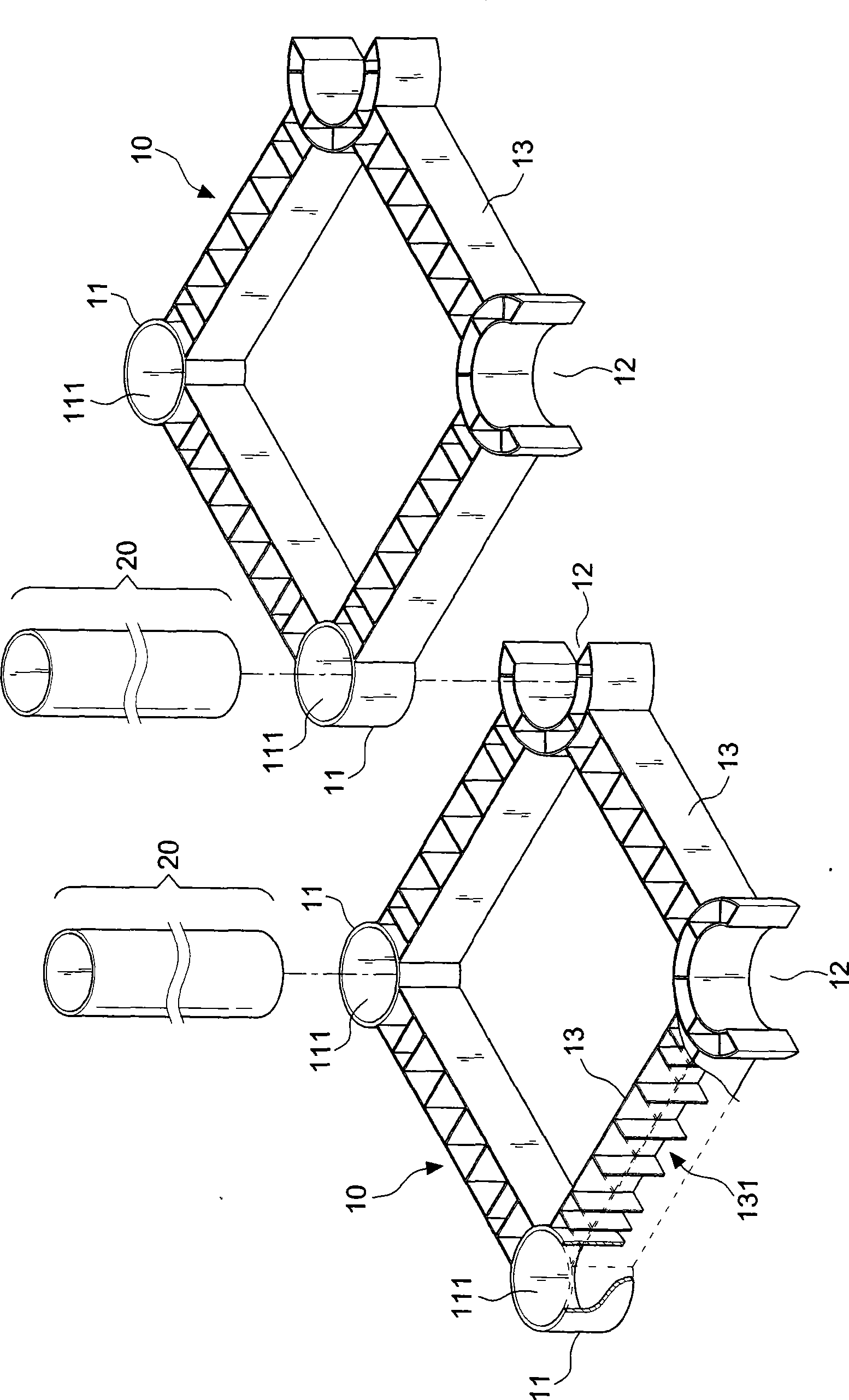
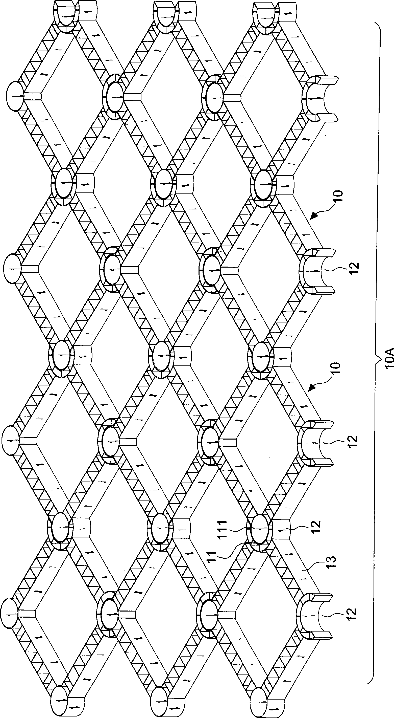
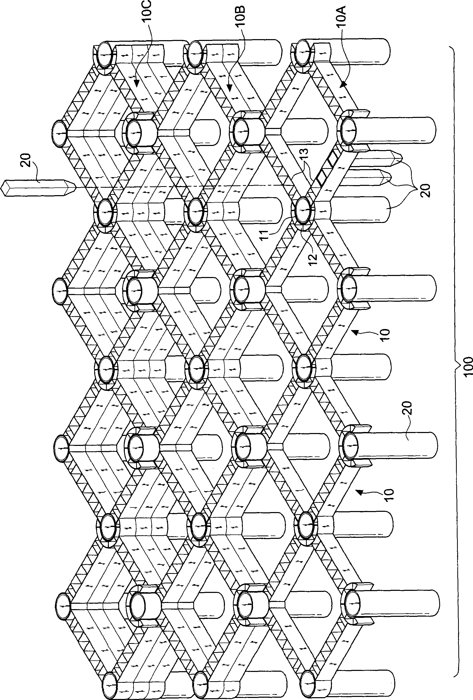
[0069] First, see Figure 1 ~ Figure 3 As shown in the first feasible embodiment of the present invention, it includes a predetermined number of grid units 10 and a certain number of binding columns 20; wherein

[0070] The grid unit 10 is preferably a modular body made of light-weight and high-strength resin-based composite materials, but is not limited thereto, such as metal-based, inorganic non-metallic composite materials, and plasticized materials. It can also be used to make grid units of lightweight hollow members. And there are two or more protruding and recessed tenons 11 and slots 12 on each side respectively. The tenons 11 and the slots 12 are structural shapes of corresponding tenons and grooves. The light hollow member Between the grid units 10 , the protruding tenons 11 are respectively inserted into adjacent and corresponding grooves 12 for mortise assembly and are connected to each other, so as to form a planar layer 10A of a predetermined frame structure.

...


PUM


Abstract

The invention relates to a joggled joint type spatial mesh structure, comprising predetermined number of mesh elements and binding columns, wherein the mesh element is constructed by two or more components in predetermined shape by a mode of two component overlapping. Each component is disposed with a convex joggle and a concave slot, which are formed in corresponding joggle-slot construction. The convex joggle extends into slot of the adjacent component for joggled joint and connection, so as to combine the component in series and to construct a continuous extendable mesh element. The continuous mesh component construction is further made into a planar layer of the spatial mesh structure, a combining column gets through the hollow portion of the component, then planar layers of the mesh structure are combined in the structural height direction, so as to construct the spatial mesh structure in tri-dimensional shape. The invention not only has construction convenience, but also uses the joggle and the combining column of the component, thus has functions of earth blocking, water drainage and earth filling.

Description

technical field [0001] The invention relates to a tenon-joint space grid structure. Background technique [0002] Nowadays, there are few cases where "space frame structure" is used in civil engineering retaining walls, embankments, and waterway structures. We know that there are probably gravity structures in which precast concrete lattice bars are stacked in a criss-cross manner, and the hollow parts are filled. Gravel grading is also used for soil retaining and drainage. In addition, wood is used to complete the grid structure in the same way. The rest is probably only the grid structure used for embankment slopes. The reason why space frame structures cannot be widely used in this type of project , mainly lies in the problems of material, node combination and construction method. For example, in the previously used space frame structure, the combination of its nodes is one of the main points of the space frame structure. However, the existing combination of nodes betwee...

Claims


Application Information

Patent Timeline
IPC IPC(8): E02D29/02E02B3/04A01G9/00E04H17/00
Inventor 黎彪钦
Owner 黎彪钦
Learn More