Articulated probe

一种铰接式、接触点的技术,应用在点坐标测量、测量装置、仪器等方向,能够解决校准耗时、校准复杂等问题

Inactive Publication Date: 2009-07-01
RENISHAW PLC
View PDF2 Cites 4 Cited by
  • Summary
  • Abstract
  • Description
  • Claims
  • Application Information

AI Technical Summary

Problems solved by technology

However, this articulated probe has the disadvantage of time-consuming calibration when in use
Moreover, the measurement system of the articulated probe installed on the existing coordinate measuring machine is a five-axis system, which makes the calibration more complicated

Method used


Image

  • Articulated probe
  • Articulated probe
  • Articulated probe

Examples


Embodiment Construction

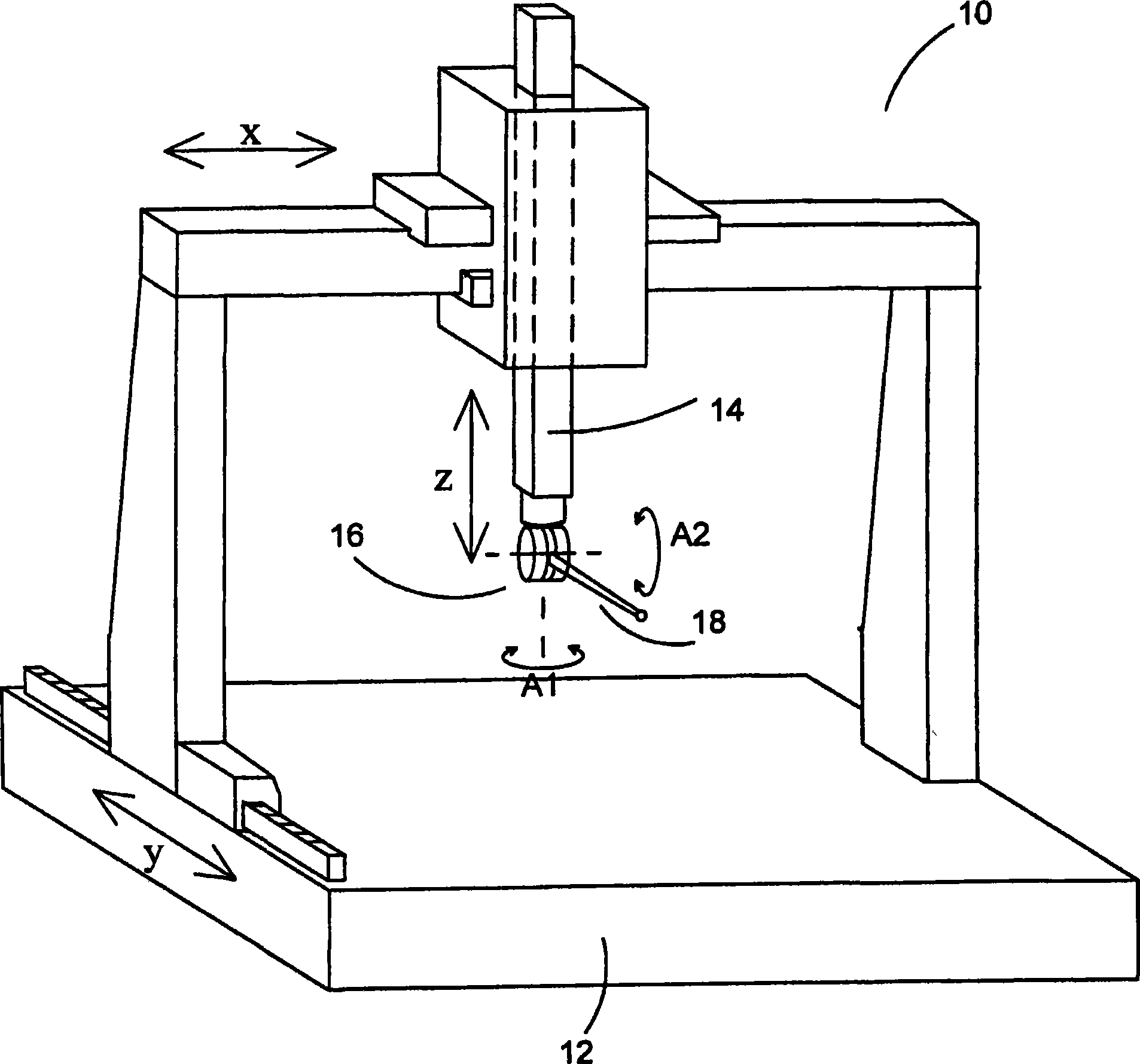
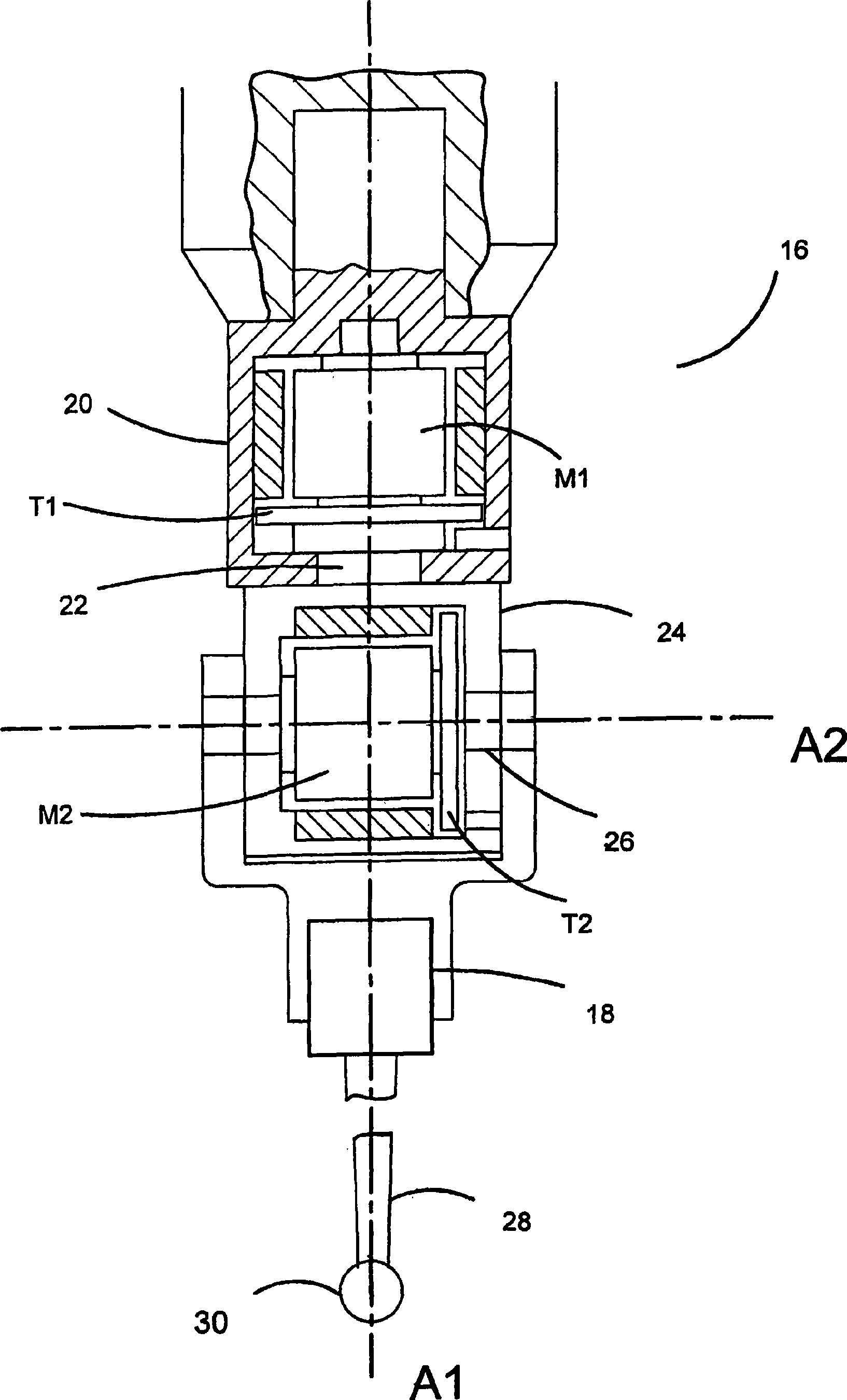
[0045] figure 1 Shown is the articulated probe mounted on the coordinate measuring machine. The coordinate measuring instrument 10 includes a platform 12 on which a workpiece can be placed and an arm 14 movable in X, Y, and Z directions relative to the platform 12. The articulated probe 16 is mounted on the arm 14 of the coordinate measuring machine (CMM). The articulated probe 16 allows the workpiece measuring probe 18 mounted thereon to rotate about two substantially vertical axes A1 and A2.

[0046]Therefore, the robot arm 14 can move in the X, Y, and Z directions under the action of the X, Y, and Z driving devices (not shown) of the coordinate measuring instrument. The scale devices (not shown) on X, Y and Z display the real-time coordinates of the position of the arm 14. A rotation drive device (not shown) located in the articulated probe can make the probe move around the two rotation axes A1 and A2. This movement is measured by a rotating scale device (not shown) located ...


PUM


Abstract

A method of calibrating an articulating probe head comprising the steps of measuring an artefact of known dimensions with the workpiece sensing probe mounted on the articulating probe head, in which the articulating probe head is unlocked. An error functional map is generated corresponding to the difference between the measured and known dimensions of the artefact. Subsequent workpieces are measured with the articulating probe head unlocked and the corresponding correction applied. The true dimensions of the artefact may be determined by measuring it with a probe mounted on an articulating probe head in which the axes of the articulating probe head are locked. A mechanical lock is provided to lock the axes of the articulating probe head.

Description

[0001] This application is a divisional application of a patent application with an application number of 200480027339.5, an application date of September 22, 2004, and an invention title of "error compensation method in coordinate measuring instrument". Technical field [0002] The invention relates to a method for measuring the size of a workpiece by using an articulated probe installed on a coordinate positioning device. Coordinate positioning devices include, for example, coordinate measuring machines (CMM), machine tools, manual coordinate measuring arms, and inspection robots. Background technique [0003] When the workpiece is produced, it is usually customary to place the workpiece on a coordinate measuring machine (CMM) for inspection. The coordinate measuring machine (CMM) has a sleeve with a probe mounted on it, in the working volume of the instrument, The probe can be driven in three orthogonal directions X, Y and Z. [0004] The CMM may use, for example, a laser inter...

Claims


Application Information

Patent Timeline
Patent Type & Authority Applications(China)
IPC IPC(8): G01B7/016G01B11/00G01B21/04
CPCG01B3/30G01B21/042G01B21/045G01B5/012
Inventor 戴维·罗伯特·麦克默特里若弗雷·麦克法兰赖清河斯蒂芬·詹姆斯·特鲁尔尼古拉斯·约翰·韦斯顿
Owner RENISHAW PLC
Why Eureka
Try Eureka