Laser bar code scanner and its execution method

A technology of laser barcode and execution method, applied in the direction of electromagnetic radiation induction, etc., can solve the problems of inability to interpret barcode 20 data, affecting reading distance and accuracy, scanning light width and intensity effect, etc., to reduce the width and improve reading. the effect of distance

Inactive Publication Date: 2009-07-01
MARSON TECH
View PDF0 Cites 11 Cited by
  • Summary
  • Abstract
  • Description
  • Claims
  • Application Information

AI Technical Summary

Problems solved by technology

[0003] However, due to the fixed swing angle of the mirror or prism in the past, the width of the scanning light is also fixed. When using a laser barcode scanner to scan a barcode, the distance between it and the barcode is often different depending on the usage conditions. But because the beam angle of the scanning light is fixed, when the distance between the laser barcode scanner and the barcode is farther, the width of the scanning light will also become larger, please refer to figure 1 , is a schematic diagram of the use of the existing laser barcode scanner, as shown in the figure, when the existing laser barcode scanner 10 scans the barcode 20 with different distances l1, l2, the width w1, w2 of the scanning light 30, Will not change with the swing angle θ of the mirror or prism, by figure 1 It can be seen that as the distance between the laser barcode scanner 10 and the barcode 20 increases (l2>l1), the width of the scanning light 30 also becomes larger (w2>w1), and compared with the scanning light 30 with a short distance , the intensity of the scanning light 30 will be relatively weaker, therefore, it may not be possible to read the data of the barcode 20, and the scanning light 30 that is too close may be limited due to power consumption, price and safety considerations. Read distance with laser barcode scanner 10
[0004] In view of the fact that the existing laser barcode scanners are often used due to the influence of distance, the width and intensity of the scanning light are affected, and even the reading distance and accuracy are affected. The inventor has studied carefully and finally designed a A New Laser Barcode Scanner and How It Is Implemented

Method used


Image

  • Laser bar code scanner and its execution method
  • Laser bar code scanner and its execution method
  • Laser bar code scanner and its execution method

Examples


Embodiment Construction

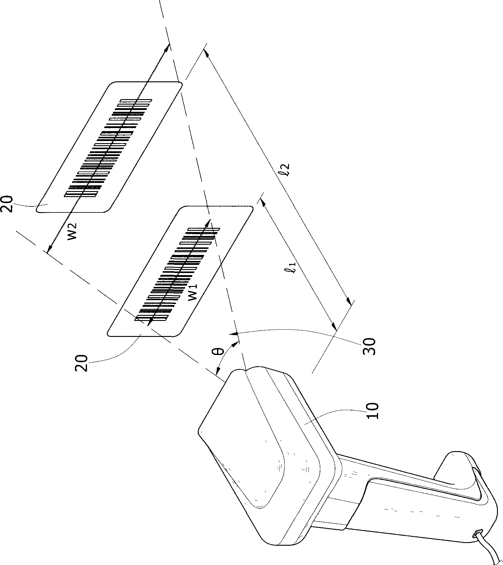
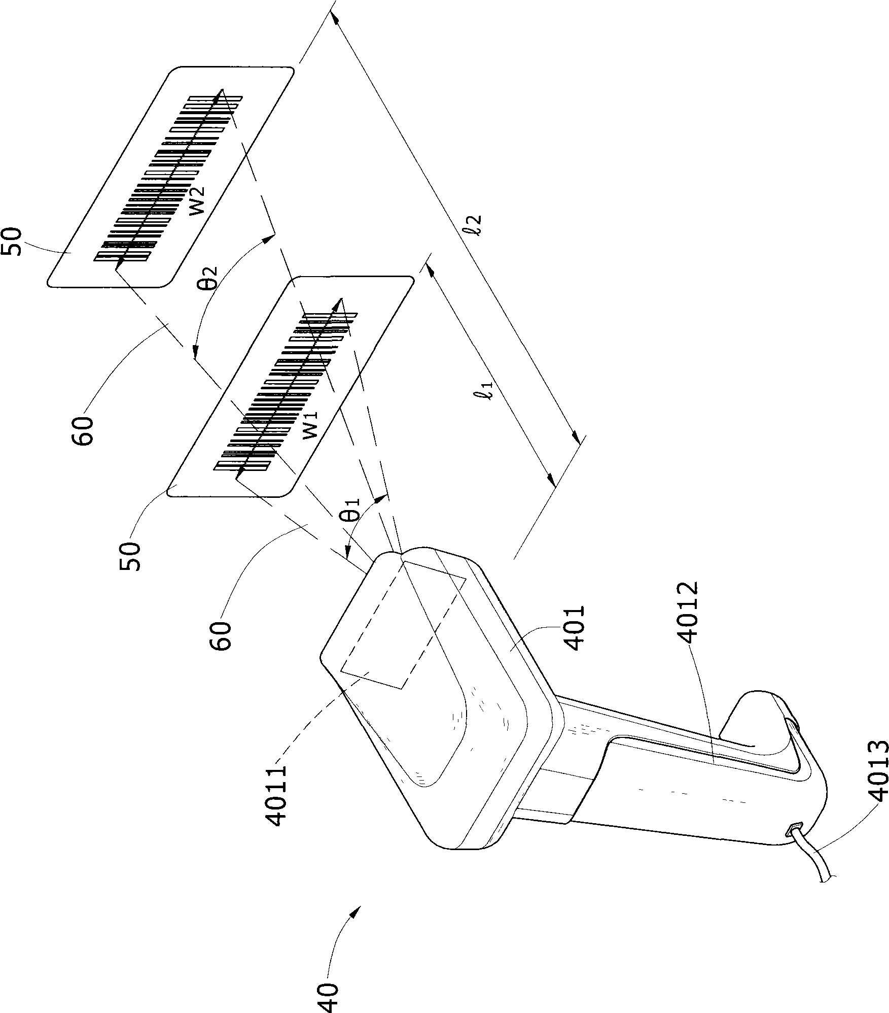
[0017] see figure 2 , is a schematic diagram of the use of a preferred embodiment of the present invention. As shown in the figure, there are two types of common laser barcode scanners 40: hand-held and seat-type. This embodiment takes the hand-held laser barcode scanner 40 as an example. The front of the housing 401 is formed with a through-hole 4011, a handle 4012 for the user to hold, and at the bottom of the housing 401, there is a signal connection with computer equipment or the purchase, sale and storage equipment. The connection line 4013, when the user operates the handheld laser barcode scanner 40, the handheld laser barcode scanner 40 can emit the ranging light and the scanning light 60, and receive it again after being reflected by the barcode 50. The present invention relies on the ranging The light is measured in advance, and when scanning the barcode 50 with different distances l1, l2, the width w1, w2 of the scanning light 60 is changed, and as the distance bet...


PUM


Abstract

The invention relates to a laser bar code scanner and an executing method thereof, wherein the method comprises rapidly measuring the distance between a laser bar code scanner and a bar code by means of the mode of light-ranging, calculating and switching signals through a signal processor, and automatically adjusting the width of scanning light transmitted by the laser bar code scanner by the rotation angles of an automatic control-rotating device at any time, and therefore, scanning light can automatically adjust correct intensity and width as the variation of the distance when being used in different distances, and the reading efficiency of the laser bar code scanner can be greatly improved.

Description

technical field [0001] The invention relates to a laser barcode scanner and its execution method which can automatically adjust the width of the scanning light to increase the reading distance by measuring the distance between the laser barcode scanner and the barcode by means of light distance measurement. Background technique [0002] The working principle of the laser barcode scanner is mainly to use a laser diode (Laser Doide) to generate a little laser light source, which is projected onto a reciprocating swinging mirror or prism, and can be transformed from a light point into a light beam, which is irradiated behind the barcode of the product , and then use the photodiode (Photo Doide) to detect the light reflected from the barcode and convert it into an electronic signal to determine the information represented by the barcode. [0003] However, due to the fixed swing angle of the mirror or prism in the past, the width of the scanning light is also fixed. When using a ...

Claims


Application Information

Patent Timeline
Patent Type & Authority Applications(China)
IPC IPC(8): G06K7/10
Inventor 刘国胜
Owner MARSON TECH
Why Eureka
Try Eureka