
High-frequency constant current source converter of neon

A technology of constant current power supply and converter, which is applied in the direction of electric light source, AC power input conversion to DC power output, output power conversion device, etc. It can solve the problems of interference with electronic equipment, large electromagnetic interference, and low output power. Achieve the effect of improving the brightness of the lamp tube, reducing radio frequency electromagnetic interference, and prolonging the life of the lamp tube

Inactive Publication Date: 2009-07-01
迈博电子技术(上海)有限公司 +2
View PDF0 Cites 4 Cited by
  • Summary
  • Abstract
  • Description
  • Claims
  • Application Information

AI Technical Summary

Problems solved by technology

[0002] The commonly used high-frequency constant-current power converter for neon lights adopts a voltage-fed double-transformer topology (that is, a voltage source power supply structure). The instantaneous overvoltage and overcurrent will cause the failure of the converter
The operating frequency of this type of structural converter is not easy to set, and the output is a rectangular wave voltage to drive the neon tube, which will generate radio frequency electromagnetic interference (RFI) caused by high-order harmonics, which has the following disadvantages:
[0003] 1. The output power is low, which makes the brightness of the neon tube dim;
[0004] 2. The constant current characteristic is poor, and the brightness is uneven when driving neon tubes of different lengths;
[0005] 3. The electromagnetic interference is too large, which interferes with the surrounding electronic equipment;
[0006] 4. The reliability of the protection circuit is low

Method used


Image

  • High-frequency constant current source converter of neon
  • High-frequency constant current source converter of neon
  • High-frequency constant current source converter of neon

Examples


Embodiment Construction

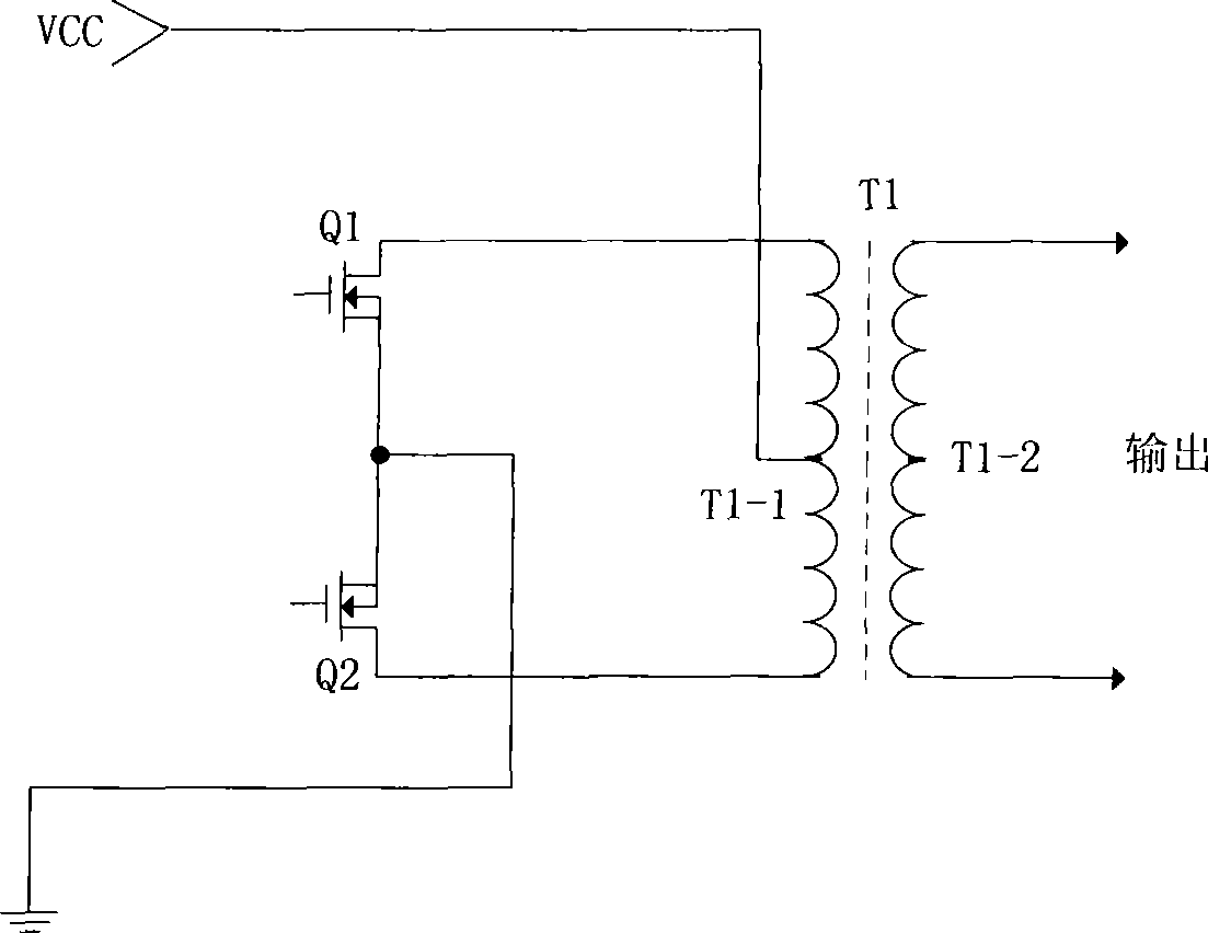
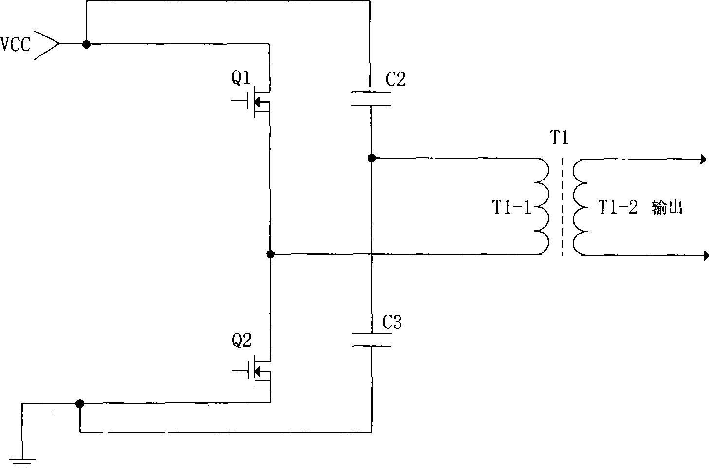
[0022] The high-frequency constant current power converter of the neon lamp of the present invention can adopt push-pull topological structure or half-bridge topological structure, as figure 1 Shown is a schematic diagram of a typical push-pull structure. The primary coil T1-1 of the flux leakage transformer has a center tap, which is connected to the power supply VCC. The two ends of the primary coil T1-1 are respectively connected to the push-pull switches Q1 and Q2. On the drain, the sources of the push-pull switches Q1 and Q2 are both connected to ground. Such as figure 2 Shown is a schematic diagram of a typical half-bridge structure, the drain of the half-bridge switch Q1 is connected to the power supply VCC, its source is connected to the drain of the half-bridge switch Q2, the source of the half-bridge switch Q2 is grounded, and the capacitors C2 and C3 are connected in series Connected to the power supply and the other end to ground, one end of the primary coil T1-1...


PUM


Abstract

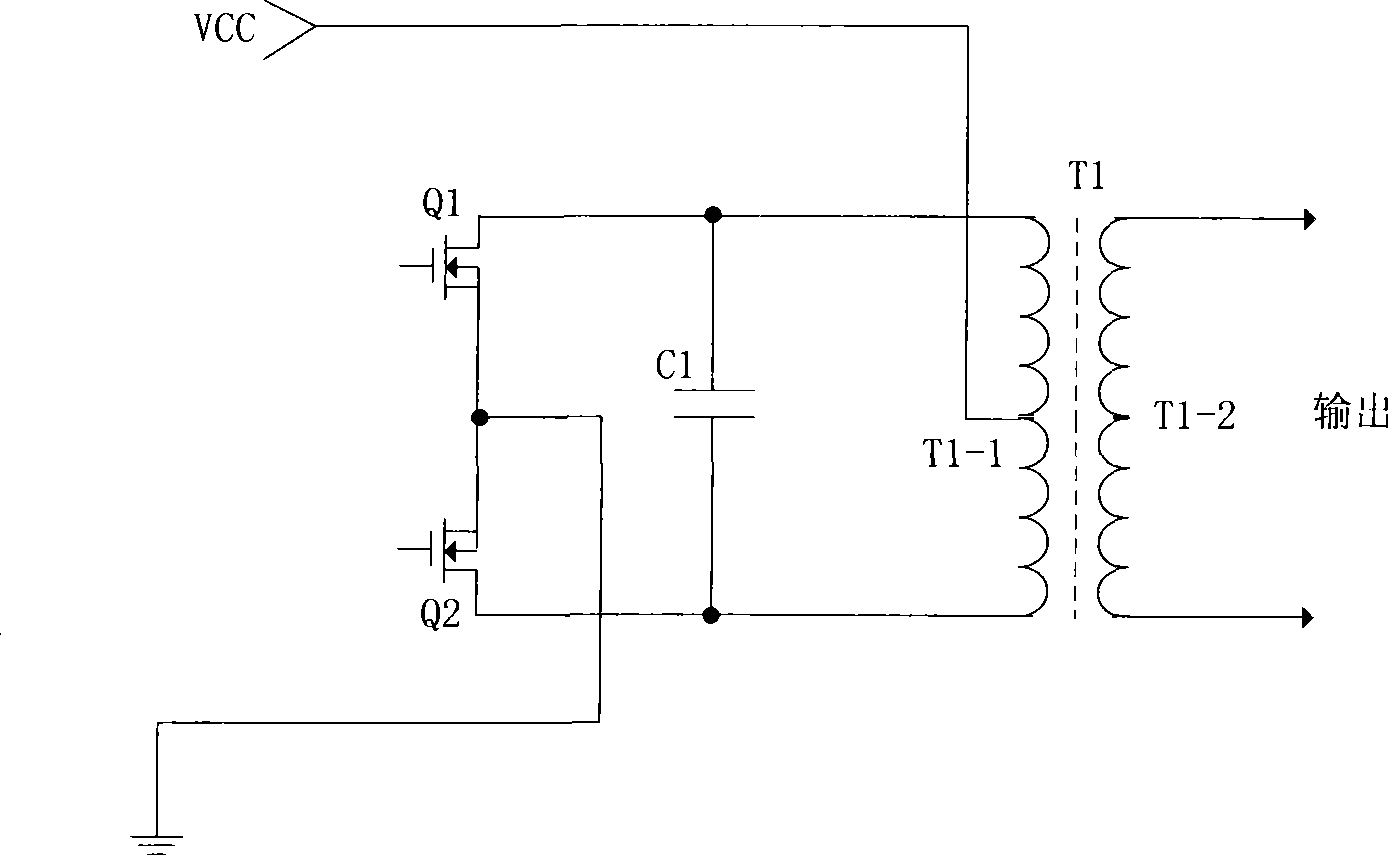
The invention discloses a converter with a high-frequency and constant current power supply of a neon light, which comprises a leakage transformer and a resonant capacitor, wherein, the resonant capacitor is connected in parallel at two ends of a primary coil of the leakage transformer, distributed capacitance and load capacitance of the primary coil of the leakage transformer are converted into the capacitance at two ends of a primary coil and the total capacitance connected in parallel with the resonant capacitance, a parallel resonance comprises the primary coil of the leakage transformer and the resonant capacitance, and the resonance frequency is: (see the following formula); wherein, f is resonance frequency, L is inductance of the primary coil, and C is capacitance at two ends of the primary coil and total capacitance connected in parallel with the resonant capacitance converted through distributed capacitance and load capacitance of the primary coil of the leakage transformer. The invention outputs sinusoidal wave voltage to drive the neon light tube through parallel resonance, and current of the neon light tube also adopts sinusoidal wave. Therefore, the brightness of the neon light tube is enhanced, the service life of the neon light tube is prolonged, and the radio-frequency electromagnetic interference caused by the higher harmonic radiation is reduced.

Description

technical field [0001] The invention relates to a high-frequency constant current power converter for neon lights. Background technique [0002] The commonly used high-frequency constant-current power converter for neon lights adopts a voltage-fed double-transformer topology (that is, a voltage source power supply structure). The instantaneous overvoltage and overcurrent will cause the failure of the converter. The operating frequency of this type of structural converter is not easy to set, and the output is a rectangular wave voltage to drive the neon tube, which will generate radio frequency electromagnetic interference (RFI) caused by high-order harmonics, which has the following disadvantages: [0003] 1. The output power is low, which makes the brightness of the neon tube dim; [0004] 2. The constant current characteristic is poor, and the brightness is uneven when driving neon tubes of different lengths; [0005] 3. The electromagnetic interference is too large, wh...

Claims


Application Information

Patent Timeline
IPC IPC(8): H05B41/295H05B41/24H02M7/523
Inventor 陈白迪陈安迪
Owner 迈博电子技术(上海)有限公司
Learn More