Six-freedom degree wearing type auxiliary bone-knitting parallel-connected robot

A wearable, degree-of-freedom technology, used in robotics, medical science, surgery, etc., can solve the problem of inability to take into account plastic reduction and fixation, and achieve the effect of reducing medical costs, reducing pain, and reducing chronic edema

Inactive Publication Date: 2009-07-08
HARBIN INST OF TECH
View PDF0 Cites 20 Cited by
  • Summary
  • Abstract
  • Description
  • Claims
  • Application Information

AI Technical Summary

Problems solved by technology

[0003] The purpose of the present invention is to solve the problem that the existing bone external fixator can only be used for fixation after fracture reduction, and cannot take into account the problem of plastic reduction and fixation at the same time, and provides a six-degree-of-freedom wearable auxiliary osteosynthetic parallel robot

Method used


Image

  • Six-freedom degree wearing type auxiliary bone-knitting parallel-connected robot
  • Six-freedom degree wearing type auxiliary bone-knitting parallel-connected robot
  • Six-freedom degree wearing type auxiliary bone-knitting parallel-connected robot

Examples


specific Embodiment approach 1

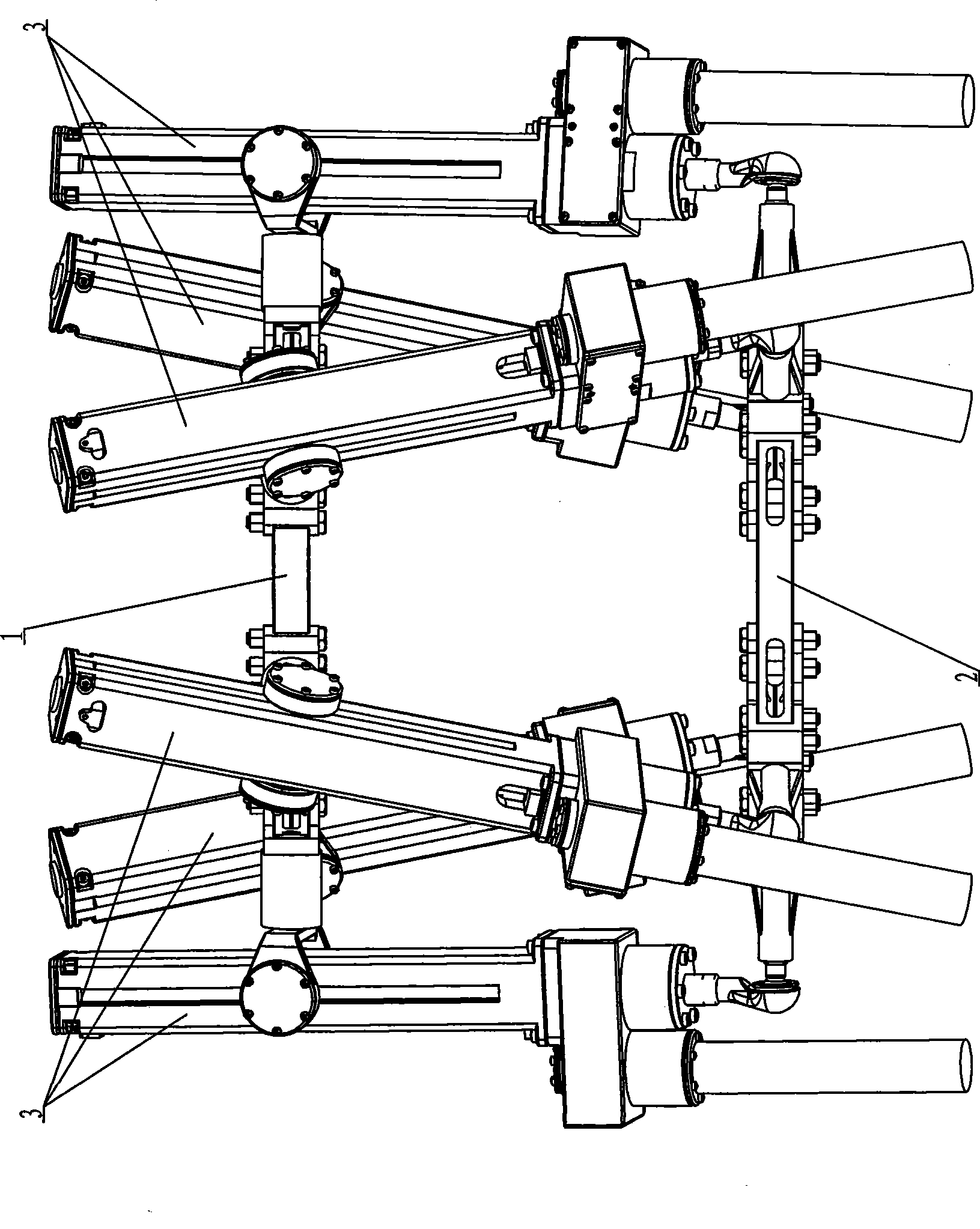
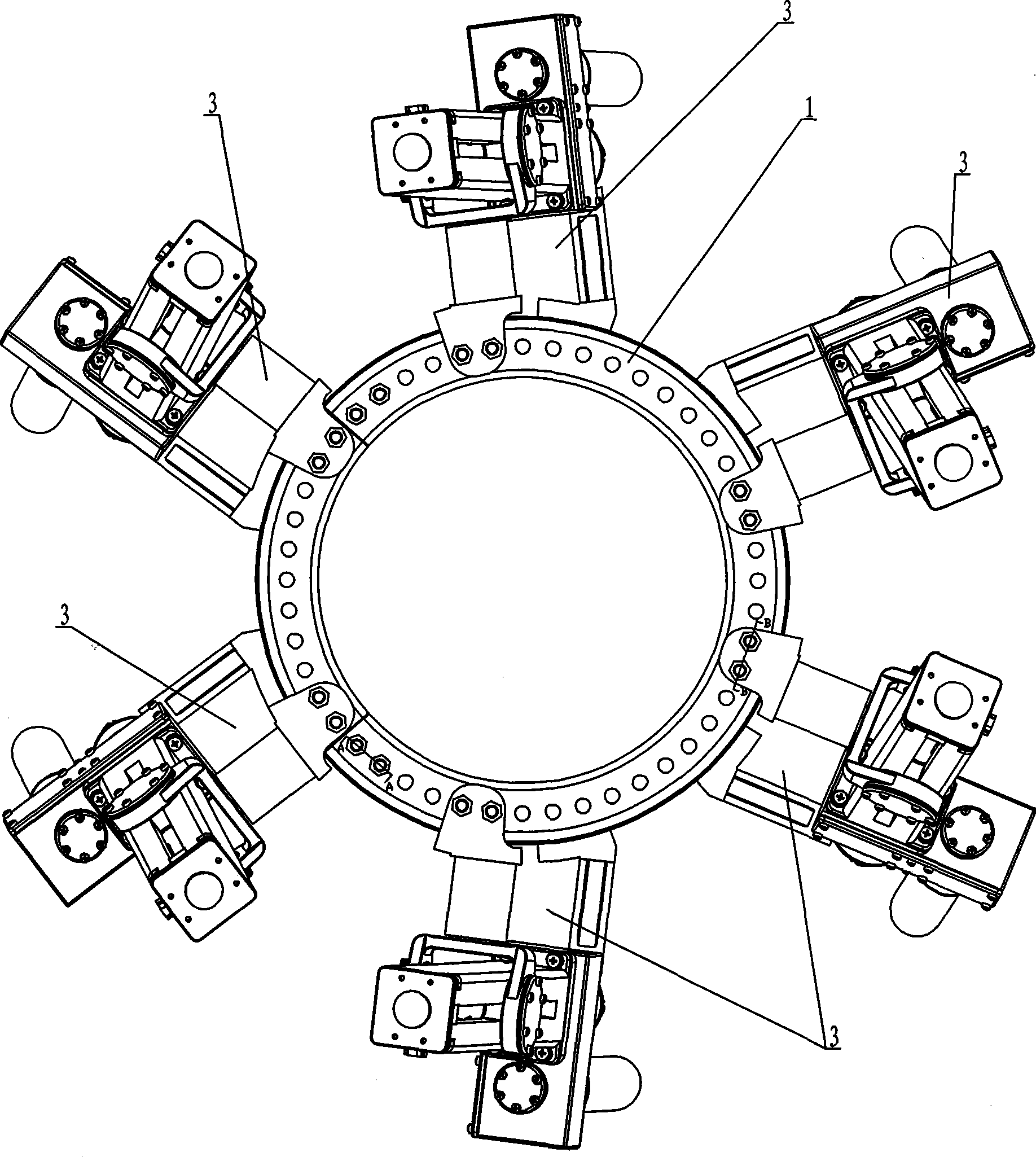
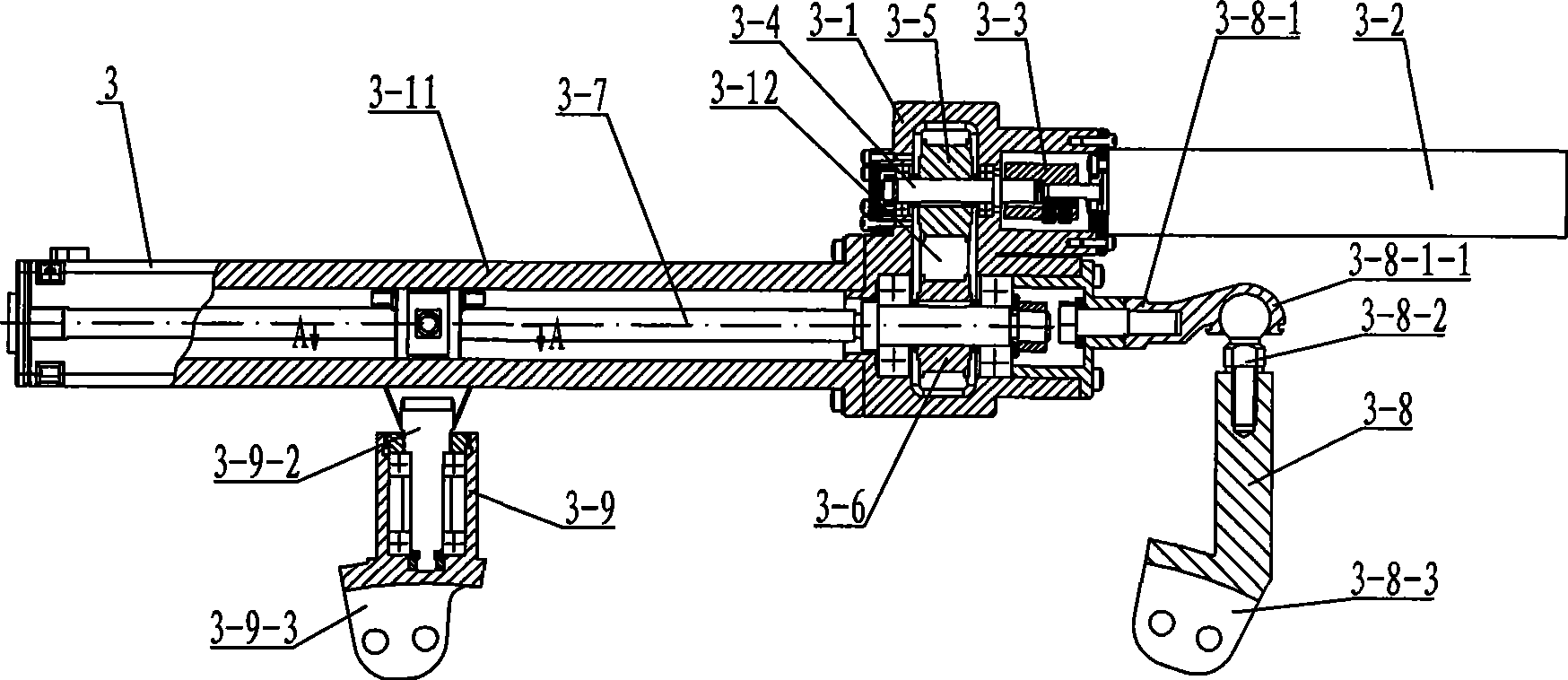
[0007] Specific implementation mode one: combine Figure 1 to Figure 5 Describe this embodiment. This embodiment is composed of a moving ring 1, a fixed ring 2 and at least three branch chains 3, and each branch chain 3 consists of a reducer housing 3-1, a motor 3-2, and a coupling 3-3 , connecting shaft 3-4, driving pulley 3-5, passive pulley 3-6, lead screw 3-7, ball hinge mechanism 3-8, Hooke hinge 3-9, nut 3-10, lead screw housing 3-11 and belt 3-12, the connecting shaft 3-4 is hinged in the reducer housing 3-1 through the bearing, the input end of the connecting shaft 3-4 is connected with the output of the motor 3-5 through the coupling 3-3 Shaft connection, the driving pulley 3-5 is set on the connecting shaft 3-4, the driving pulley 3-5 is connected with the passive pulley 3-6 through the belt 3-12, and the passive pulley 3-6 is set on the screw 3- 7, the screw 3-7 is hinged in the reducer housing 3-1 through the bearing, the screw 3-7 is installed in the screw housin...

specific Embodiment approach 2

[0008] Specific implementation mode two: combination image 3 and Figure 6 Describe this embodiment, the Hooke hinge 3-9 of this embodiment is made up of two Hooke hinge clamps 3-9-1, Hooke hinge clamp handle 3-9-2 and Hooke hinge mounting block 3-9-3 , the two Hooke hinge clamps 3-9-1 are symmetrically arranged and connected with the upper end of the Hooke hinge handle 3-9-2, and the lower end of the Hooke hinge handle 3-9-2 is hinged on the Hooke hinge through bearings In the block 3-9-3, the axis of the Hooke hinge mounting block 3-9-3 is perpendicular to the axes of the two Hooke hinge clamps 3-9-1. The two Hooke hinge clips 3-9-1 are fixedly connected with the nuts 3-10 through bolts respectively, and the lower end of the Hooke hinge mounting block 3-9-3 is fixedly mounted on the moving ring 1 through bolts. The Hooke hinge mounting block 3-9-3 can rotate arbitrarily around its axis, and the Hooke hinge clamp 3-9-1 cannot rotate.

specific Embodiment approach 3

[0009] Specific implementation mode three: combination image 3 Describe this embodiment, the ball joint mechanism 3-8 of this embodiment is made up of ball joint mounting plate 3-8-1, ball joint 3-8-2 and ball joint connecting plate 3-8-3, ball joint mounting plate 3 One end of -8-1 is fixed on the reducer housing 3-1, the other end of the ball hinge mounting plate 3-8-1 is provided with a ball hinge shell 3-8-1-1, and the ball hinge 3-8-2 The ball end of the ball joint is hinged in the ball joint shell 3-8-1-1, and the handle end of the ball joint 3-8-2 is threadedly connected with the ball joint connecting plate 3-8-3. The other end of the ball hinge connecting plate 3-8-3 is fixedly mounted on the fixed ring 2 by bolts. The spherical hinge 3-8-2 can rotate freely on the axis of the spherical hinge connecting plate 3-8-3, and the range of motion of the axis of the spherical hinge connecting plate 3-8-3 is a ball center on the spherical hinge 3-8-2 A cone with vertices.


PUM


Abstract

A six degree of freedom wearable auxiliary bone-knitting parallel connection robot relates to a robot device used in medical treatment. The invention solves the problem that an existing skeletal external fixation can only be used for fixation after reduction of the fracture and can not give attention to the problems of the shaping replacement carried out on simultaneously with the fixation. A connecting shaft is articulated in a shell of a reducer. The input end of the connecting shaft is connected with the output shaft of a motor. An initiative belt wheel is sheathed on the connecting shaft and is connected with a passive belt wheel by a leather belt. The driven belt wheel is sheathed on a guide screw which is articulated in the shell of the reducer and arranged in the shell of the guide screw. The shell of the guide screw is fixedly arranged on the shell of the reducer. A nut is sheathed on a guide screw. One end of a hook joint is connected with the nut and the other end of the hook joint is fixedly arranged on a primary ring. One end of a spherical hinge mechanism is fixedly arranged on the shell of the reducer and the other end is fixed on the primary ring. Combined with the external bone fixation technology, the parallel connection robot can assist doctors to finish the exact position of the surgery place and realizes that the shaping replacement and the fixation of fracture are carried out simultaneously.

Description

technical field [0001] The invention relates to a medical robot device, in particular to a parallel robot for assisting bone setting. Background technique [0002] In robot-assisted orthopedic surgery at home and abroad, robots are mainly used to assist doctors to complete functional operations such as operating instruments and navigating. At present, there are mainly two types of fixation for long limb bones in orthopedic surgery: internal fixation and external fixation. Internal fixation refers to the fixation of intramedullary nails; external fixation is the use of external fixators to fix the limbs outside the body. Most of the external fixators adopt a circular sleeve structure and are fixed with multi-directional needles. The stability of fixation is related to the number of nails and connecting rods used. related. But the existing bone external fixator can only be used for fixation after fracture reduction, and cannot take both functions of plastic reduction and fix...

Claims


Application Information

Patent Timeline
Patent Type & Authority Applications(China)
IPC IPC(8): A61B17/56B25J1/00
Inventor 杜志江孙立宁张峰峰
Owner HARBIN INST OF TECH
Why Eureka
Try Eureka