
Self-circulation jet agitation device for slurry in flue gas desulfurization slurry pool

A desulfurization slurry and slurry tank technology, which is applied in transportation and packaging, mixers, fluid mixers, etc., can solve the problems of difficult slurry stirring effectively, increased energy consumption in stirring operation, and increased initial investment in the stirring system. Increased reliability and operational efficiency, reduced investment and operational energy consumption, and reduced maintenance effort

Active Publication Date: 2012-12-19
浙江菲达环保科技股份有限公司
View PDF1 Cites 0 Cited by
  • Summary
  • Abstract
  • Description
  • Claims
  • Application Information

AI Technical Summary

Problems solved by technology

However, using the air flow to stir the slurry in the oxidation tank will encounter some engineering practical problems. First, it is necessary to provide this stirring system with an ultra-high exhaust pressure (according to the actual engineering desulfurization absorption tower oxidation tank slurry liquid level height, at least More than 0.15MPa) and super large air compressor equipment, which will not only increase the initial investment of the mixing system, but also greatly increase the energy consumption of the mixing operation; moreover, the air density is relatively small, it is difficult to compare its density At least twice as high as the slurry for effective agitation; in addition, the air jet pipe of the wind slurry mixing system is usually upward, so that the precipitated solid particles of the slurry are easy to deposit and crystallize in the air jet pipe, resulting in blockage of the air jet pipe and affecting the performance of the stirring system. normal operation

Method used


Image

  • Self-circulation jet agitation device for slurry in flue gas desulfurization slurry pool
  • Self-circulation jet agitation device for slurry in flue gas desulfurization slurry pool

Examples


Embodiment Construction

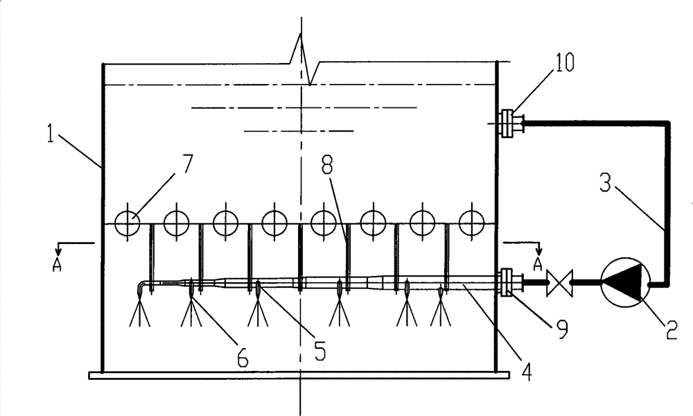
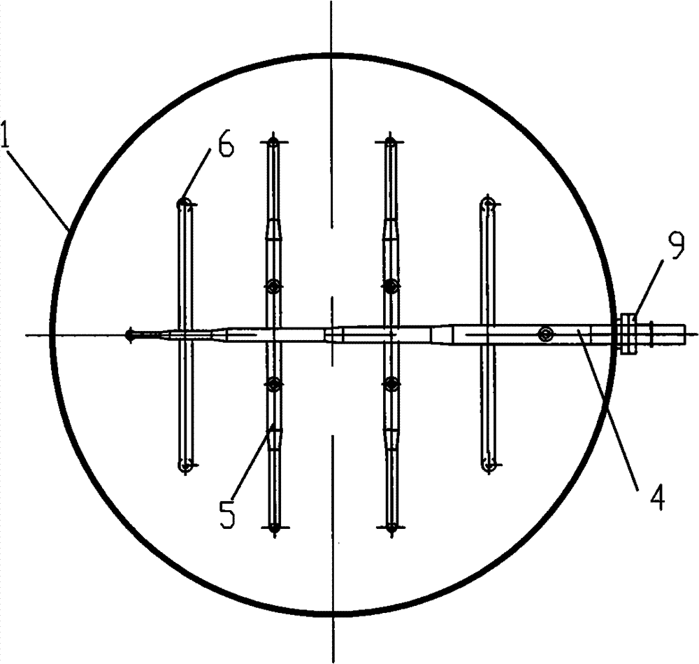
[0015] refer to figure 1 , 2 , the invention of this embodiment includes a slurry tank 1, a slurry pump 2, a circulating slurry main pipe 3, a spray slurry main pipe 4, a spray slurry branch pipe 5, a slurry nozzle 6, a pool separator 7, a bracket 8, a first flange 9, a second Flange10. The slurry pool 1 is a cylindrical shell, and the pool separator 7 is a tube array plane arranged at a certain interval by several hollow circular tubes, supported by the shell side of the slurry pool 1, installed inside the slurry pool 1, and the slurry The tank 1 is divided into upper and lower spaces. There are round holes on the sides of the upper space and the lower space of the slurry tank 1, and they are seamlessly welded with the second flange 10 and the first flange 9 respectively, and the slurry main pipe is sprayed. 4 Installed in the lower space of the slurry tank 1, its inlet is connected to the outlet of the slurry pump 2 outside the slurry tank 1 through the first flange 9 and ...


PUM


Abstract

The invention discloses a flue gas desulfurization grout pond self circulation jet agitation device, which comprises a grout pond. The grout pond is internally provided with a pond separator by which the grout pond is split into an upper room and a lower room. The upper part space of the grout pond is provided with an injection grout main pipe which is distributed with a plurality of injection grout branch pipes. The injection grout main pipe is connected with a grout pump which is connected with the upper part space of the grout pond by a circulation grout main pipe. The device takes the grout in the grout pond as an agitation medium, and simultaneously uses the action of Coriolis force, generates more effectual agitation effect on the grout pond, solves the problem of difficult sealing of an oblique cutting mechanical type stirrer. Potted components of the stirrer device do not need to be often replaced, thus greatly reducing maintenance workload. And the injection direction of a grout nozzle is downward; therefore, the device does not have the blockage problem of the nozzle, has better agitation effect and the energy consumption of the device is drastically reduced.

Description

【Technical field】 [0001] The invention relates to the field of environmental protection equipment, in particular to a self-circulating jet stirring device for slurry in a flue gas desulfurization slurry pool. 【technical background】 [0002] When the circulating slurry of the wet flue gas desulfurization system contacts with the flue gas, sulfite is mainly formed first, and the sulfite generally needs to be oxidized into sulfate with oxidizing air. Keep stirring to avoid sedimentation and scaling in the slurry in the pool. Therefore, the agitator equipped with the oxidation tank of the absorption tower is the key equipment of the wet desulfurization system, and the performance of this equipment is directly related to the stability and reliability of the desulfurization system. In general engineering practice, the circulating slurry tank of the desulfurization tower is stirred by an oblique agitator. In order to prevent the slurry from leaking out, the desulfurization tower h...

Claims


Application Information

Patent Timeline
Patent Type & Authority Patents(China)
IPC IPC(8): B01D53/80B01F13/02B01F5/04B01F33/40
Inventor 戴永阳许铨安舒英钢朱建波周洪棋傅峡裴磊
Owner 浙江菲达环保科技股份有限公司
Learn More