

Technique and equipment for processing reinforced thermoplastic plastic pipe
A technology for enhancing thermoplasticity and production process. It is used in tubular articles, applications, household appliances, etc. It can solve the problems of too many consumables, high pressure, high burst pressure, etc., and achieve stable and reliable work, simple equipment structure, and technological process. simple effect
- Summary
- Abstract
- Description
- Claims
- Application Information
AI Technical Summary
Problems solved by technology
Method used
Image

Examples
Embodiment
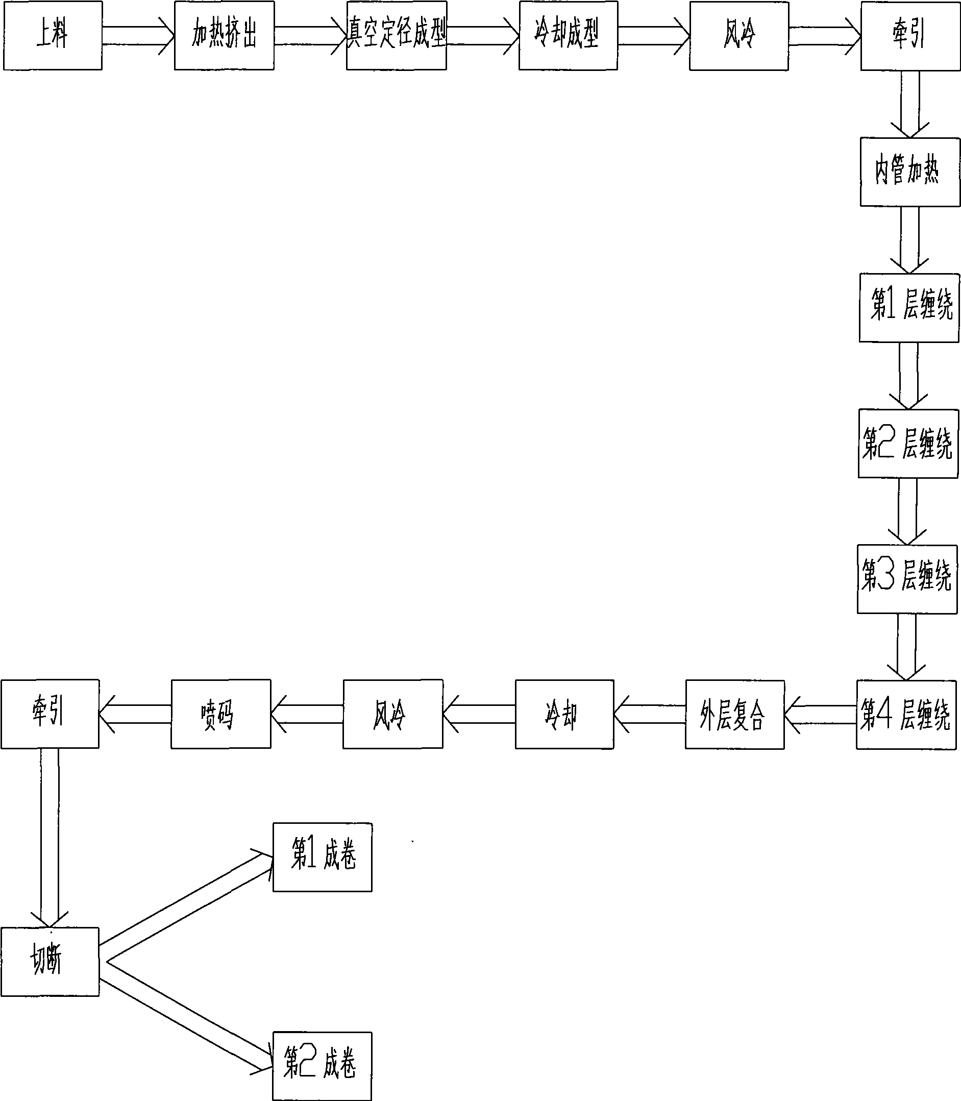
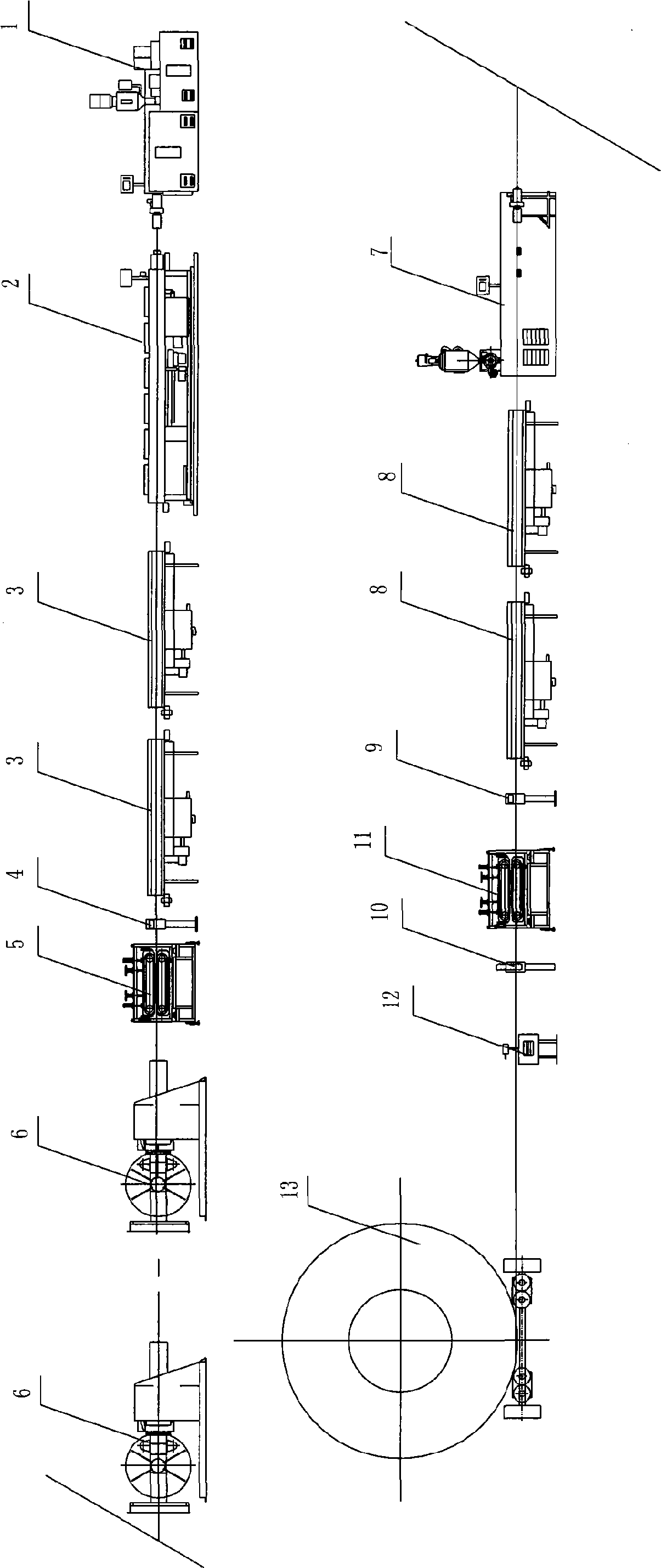
[0034] The production technology of RTP pipe of the present invention comprises the following steps:
[0035] 1) Send granular PE to the hopper of extruder 1 with negative pressure;
[0036] 2) The first extruder 1 heats the PE plastic and extrudes it through the die head continuously at a relatively high pressure;
[0037] 3) The melted PE passes through the vacuum sizing sleeve of the vacuum water tank 2, and is water-cooled and shaped into a PE inner pipe in negative pressure;
[0038] 4) The PE inner pipe continues to cool and form in the spray tank 3;
[0039] 5) The first air cooler 4 blows the surface of the PE inner pipe taken out from the spray tank to dry;
[0040] 6) Tractor 5 continuously and stably pulls the PE inner pipe to provide the power for forming the PE inner pipe;
[0041] 7) The winding machine 6 winds the plastic-coated reinforcement tape made of steel wire or fiber wire into a rope in opposite directions at a constant tension on the PE inner pipe or...
PUM
 Abstract
Description
Claims
Application Information