Inner air-cleaning system of vehicle

A technology for purifying system and in-vehicle air, applied in air treatment equipment, vehicle parts, transportation and packaging, etc., can solve problems such as affecting the efficiency of photocatalytic air purifiers, failing to achieve oxidative decomposition of polluting gases, and lack of effective means, etc. Achieve the effect of improving complete oxidative decomposition ability, improving photocatalytic removal efficiency and prolonging service life

Inactive Publication Date: 2009-07-08
中投亿星新能源投资有限公司
View PDF0 Cites 23 Cited by
  • Summary
  • Abstract
  • Description
  • Claims
  • Application Information

AI Technical Summary

Problems solved by technology

However, since the photocatalytic reaction is a surface reaction, whether low-concentration pollutants can fully contact the surface of the catalyst, and whether the photons emitted by the light source can excite the catalyst to generate more electrons and holes , are the main issues affecting the efficiency of photocatalytic air purifiers
[0004] (2) Activated carbon is an important adsorbent for removing polluted gases by physical methods. It has a large specific surface and has a strong ...

Method used


Image

  • Inner air-cleaning system of vehicle
  • Inner air-cleaning system of vehicle
  • Inner air-cleaning system of vehicle

Examples


Embodiment approach 1

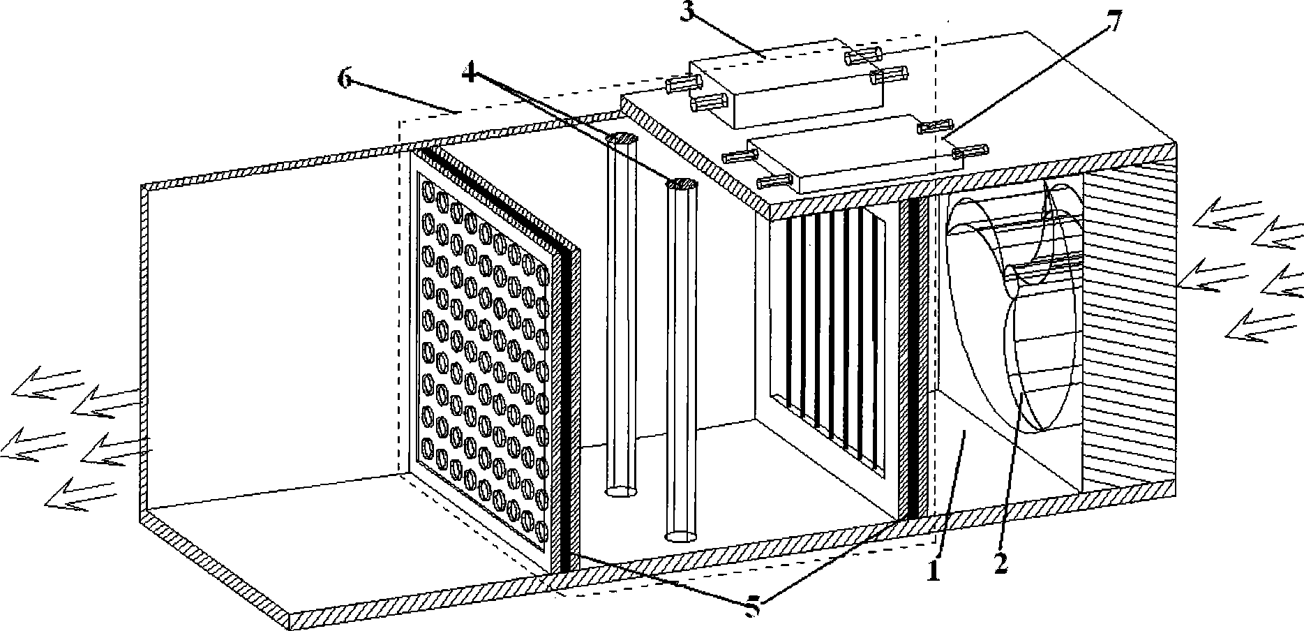
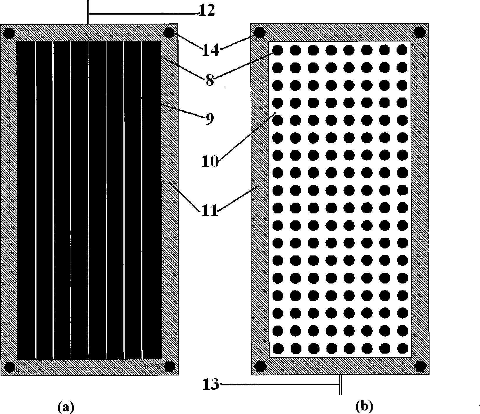
[0028] Such as figure 1 Shown is a schematic structural diagram of the air duct 1 and the purification unit 6 in the air purification system in the car. The cross section of the air duct 1 is rectangular, and the polluted gas is introduced into the interior of the purification unit 6 through the air-inducing fan 2. The structure of the purification unit 6 is: parallel arrangement 2 plasma electrode structures and the catalyst film 5, 2 to 4 ultraviolet lamps 4 are arranged between the 2 plasma electrode structures and the catalyst film 5, and the function of the transformer 3 is to convert the primary side voltage (the 12V DC power supply used by the car) ) into a high pressure that can excite the plasma structure to generate a high-energy plasma. At the same time, the ballast 7 can directly supply power to the ultraviolet lamp 4 through a 12V DC power supply; the transformer 3 and the ballast 7 are arranged outside the air duct 1 . After the polluted gas passes through the p...

Embodiment approach 2

[0032] Such as Figure 6 As shown, the specific process is similar to Embodiment 1, except that two purification units 6 are arranged in the air duct, and the two purification units 6 are arranged as three plasma electrode structures and two sets of ultraviolet lamps 4 are arranged between the catalyst membrane 5 .

Embodiment approach 3

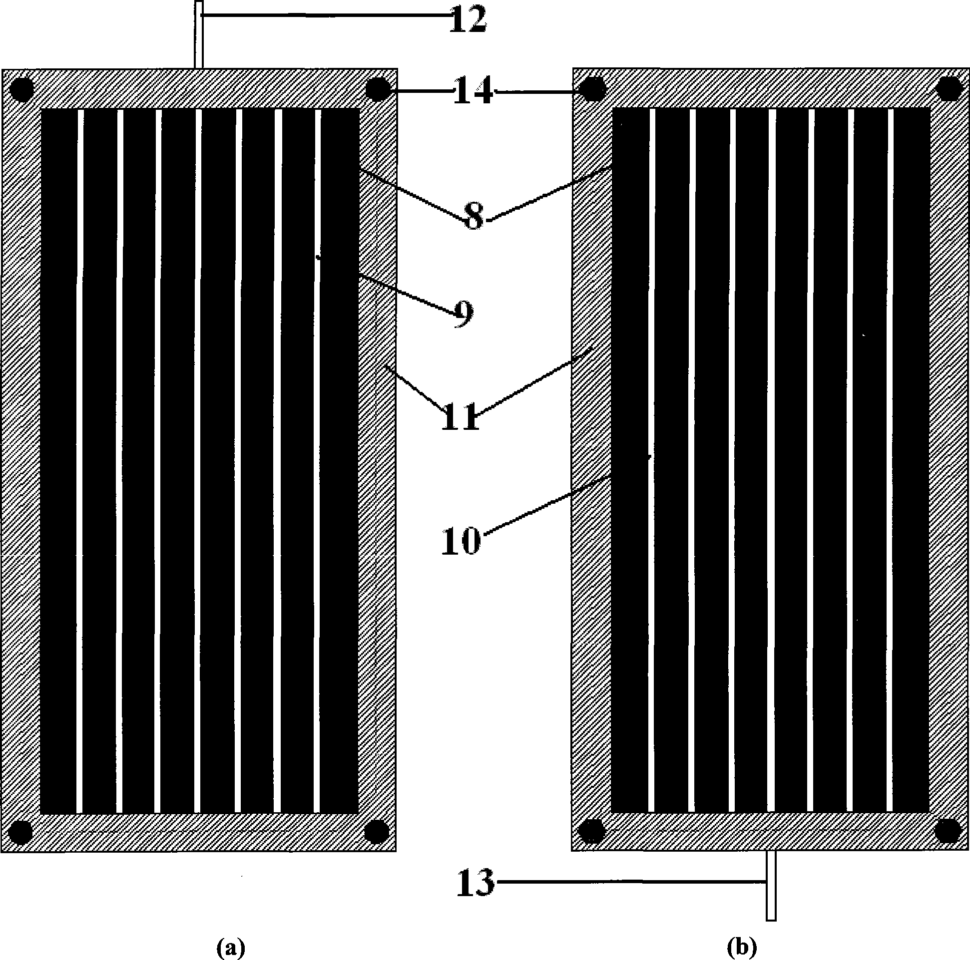
[0034] Such as Figure 7 As shown, the specific process is similar to Embodiment 1, except that the two electrode structures in the purification unit 6 are opposite to the catalyst membrane 5 at a certain angle, forming a wedge-shaped surface and placed in the air duct to increase the pollution between the polluted gas 1 and the catalyst membrane. 8 contact area.


PUM


Abstract

The invention relates to a vehicle air purification system, belongs to the field of air purifier and in particular relates to a vehicle air purification system integrating nanometer photocatalytic air purification technology, low-temperature plasma technology and active carbon adsorption technology into a whole. The system comprises a fan for introducing polluted air into the purification system; the inside of the purification system is provided with a plasma electrode structure and a catalyst membrane 5; an ultraviolet lamp 4 is arranged between the plasma electrode structure and the catalyst membrane 5 in parallel arrangement; and the outside of the purification system is provided with a transformer 3 and a ballast 7 which are connected with two electrodes of the electrode structure and the ultraviolet lamp. The system combines and applies the nanometer photocatalytic technology, the low-temperature plasma technology and the active carbon adsorption technology into the vehicle air purification system; and the synergistic action of three kinds of technology can overcome respective limitation so as to achieve the effect of removing pollutants at high efficiency.

Description

technical field [0001] The invention belongs to the field of environmental protection, in particular to an air purification system used in the interior of a car. Background technique [0002] From the production to the use of vehicles, a series of processes are accompanied by the generation of pollutants. The production process mainly has the following methods: 1) When the vehicle is produced, a large amount of plastic products and adhesives are used for the interior parts of the vehicle. , its main components include formaldehyde, benzene, xylene, acetone, etc., which are the chief culprits of environmental pollution in the car; 2) After the engine has been running for a long time, the heat generated by it will increase the volatilization of pollutants in the car; If the air conditioner is not cleaned and maintained for a long time, a large amount of dirt will adhere to the inside, and the harmful substances such as amine, nicotine, and bacteria produced will permeate the s...

Claims


Application Information

Patent Timeline
IPC IPC(8): B60H3/00B60H3/06A61L9/22A61L9/20A61L9/014A61L101/04
Inventor 鹿院卫马重芳王丁会吴玉庭
Owner 中投亿星新能源投资有限公司
Why Eureka
Try Eureka