Detection method and detection system for battery service time

A detection system and detection method technology, applied in the direction of measuring electricity, measuring devices, measuring electrical variables, etc., can solve the problems of low frequency of use of the phone, different power consumption, and inability to calculate the battery, so as to facilitate charging and prevent data loss. Effect

Inactive Publication Date: 2009-07-08
HUAQIN TECH CO LTD
View PDF0 Cites 32 Cited by
  • Summary
  • Abstract
  • Description
  • Claims
  • Application Information

AI Technical Summary

Problems solved by technology

However, under normal circumstances, the frequency or function of the electronic device used by the user in different time periods of the day will cause the electronic device to consume different power in different time periods. More, the frequency of use is higher, and the power consumption is more; while in the sleep time, because the frequency of use of the phone is low, it is in st

Method used


Image

  • Detection method and detection system for battery service time
  • Detection method and detection system for battery service time
  • Detection method and detection system for battery service time

Examples


Embodiment 1

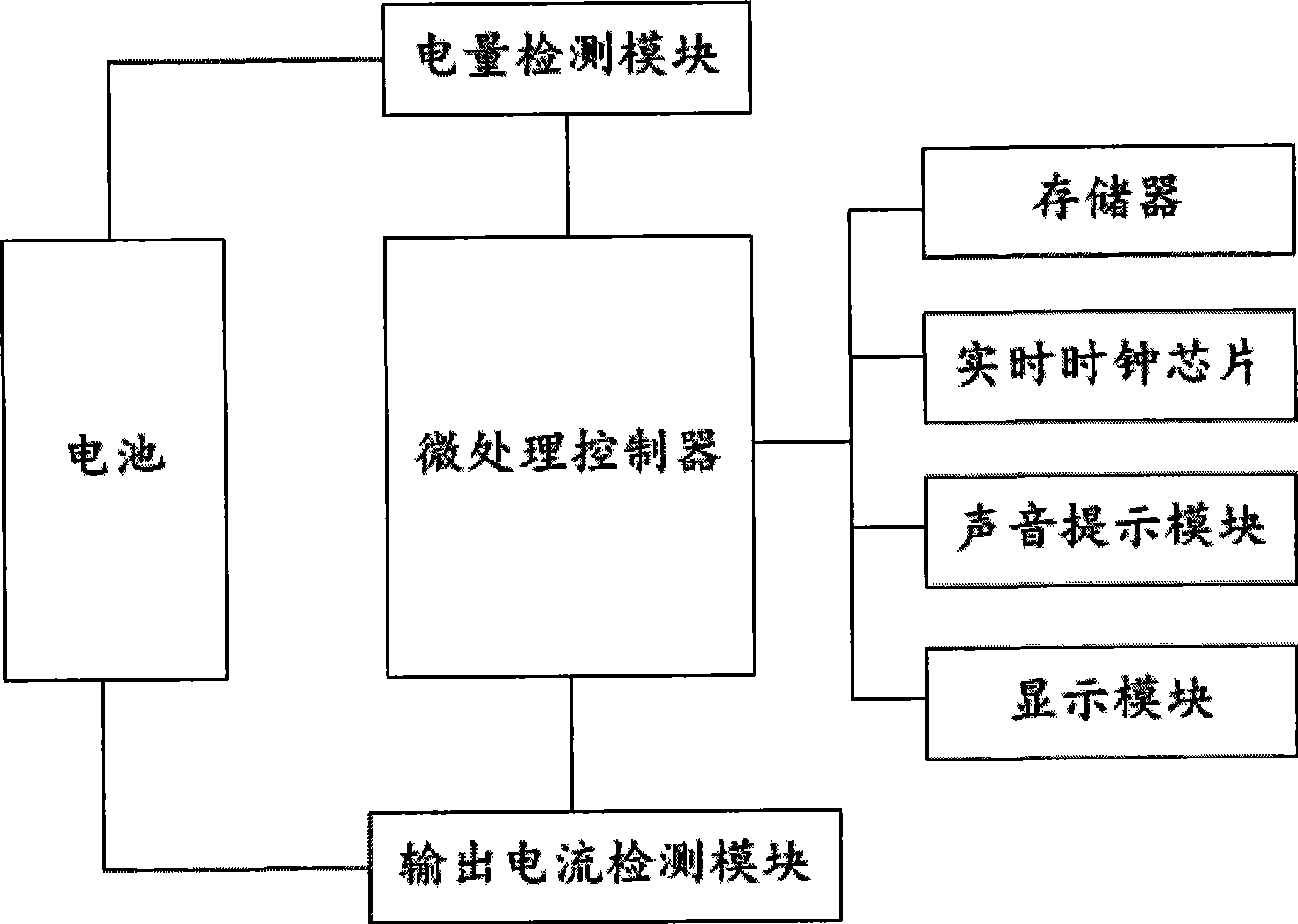
[0018] Such as figure 2 Shown, a kind of detection system of battery service time is characterized in that comprising:

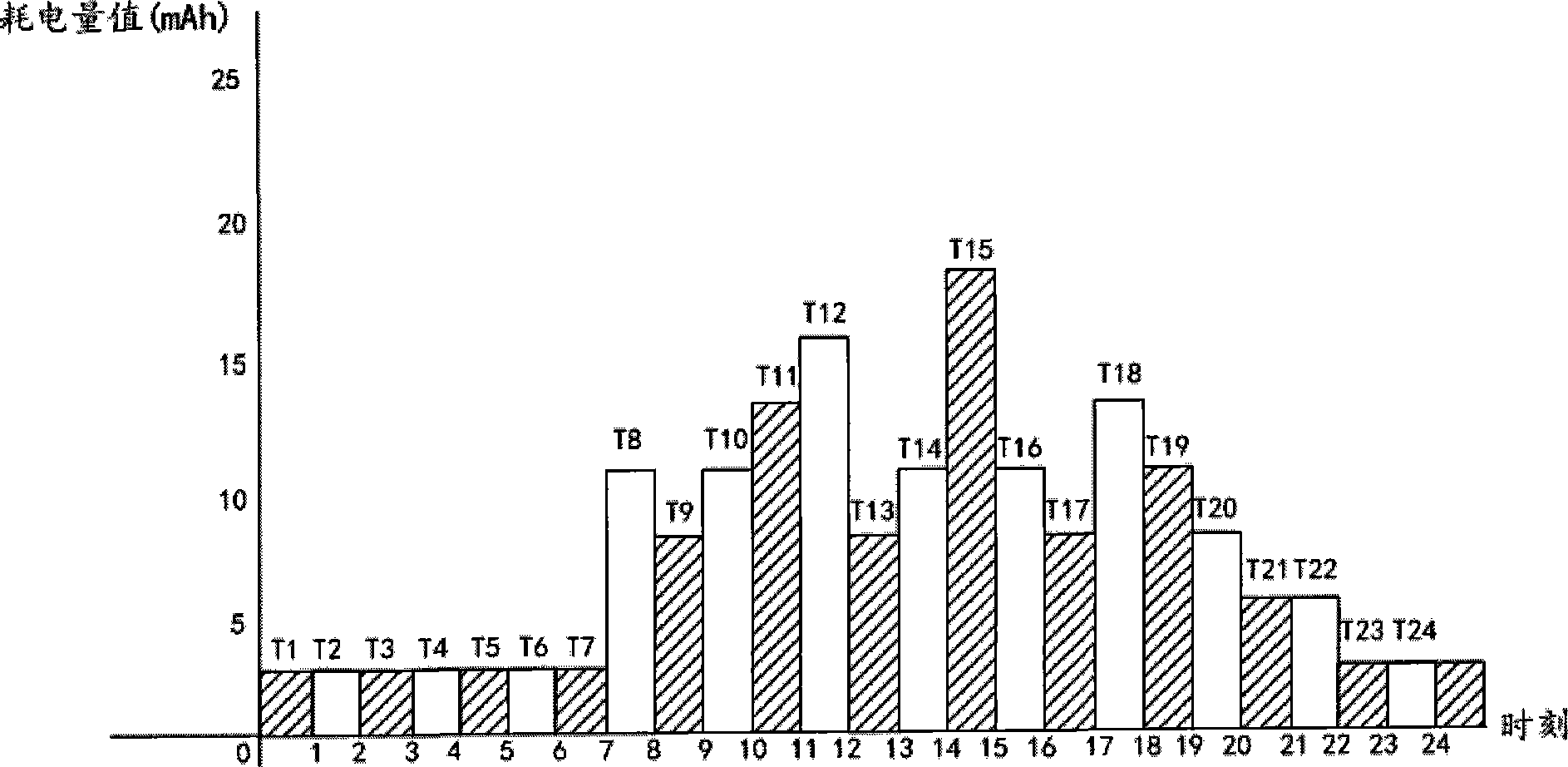
[0019] The microprocessor controller is used to calculate the power consumption value of the electronic device in each time interval of the day and calculate the current remaining power value according to the above power consumption value to support the duration of use of the electronic device; through the electronic device The power consumption value in each time interval of the day can be used to understand the distribution of the battery power consumption of the electronic device in a day (such as figure 1 shown).

[0020] The memory is used for storing the power consumption value of the electronic device in each time interval of the day, and the memory is connected with the microprocessor controller.

[0021] The power detection module is used to detect the remaining power value of the battery at the current moment and send a power signal, the input e...

Embodiment 2

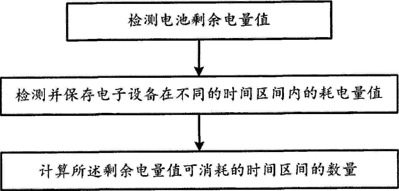
[0027] Such as image 3 As shown, a detection method for implementing the detection system described in Embodiment 1 to detect the battery life, including step 1), detecting the remaining power value of the battery; it is characterized in that it also includes:

[0028] Step 2), detect and save the power consumption value of the electronic device in different time intervals; that is, the power consumption distribution of the electronic device in a day (such as figure 1 shown);

[0029] Step 3), according to the power consumption value of the battery in different time intervals, calculate the number N of time intervals in which the remaining power value can be consumed.

[0030] Further, said step 2) includes:

[0031] Step 21), periodically detect and save the output current value I of the battery;

[0032] Step 22), calculate the power consumption value in each time interval according to I. For example, the output current value I of the battery can be detected every minut...


PUM


Abstract

The invention discloses a method and a system for detecting using time of a cell. The detection system comprises a microprocessing controller, a memorizer, an electric quantity detection module and an output current detection module. The detection method comprises: detecting the residual electric quantity of the cell; detecting and storing electricity consumption values of electronic equipment in different time intervals; and according to the electricity consumption values of the cell in different time intervals, calculating number N of the time intervals where the residual electric quantity can be consumed. The method and the system for detecting the using time of the cell can calculate duration of the residual electric quantity of the cell for supporting the use of the electronic equipment according to different time intervals. With the method and the system, a user can more accurately know the time for the electronic equipment to be used, and is convenient to charge more timely or store relevant data in time to prevent data from losing.

Description

technical field [0001] The invention relates to a detection method and a detection system for battery service time. Background technique [0002] With the rapid development of electronic technology, portable electronic devices, such as mobile phones, notebook computers, cameras, etc., play an increasingly important role in people's daily work, study and life. Utilizing a battery as a power source for these electronic devices is an important factor for the electronic devices to achieve their portability. When the remaining power of the battery cannot meet the function or duration of use of the electronic device, it is necessary to charge the battery or replace a battery with sufficient power before use. This requires the electronic device to have the function of detecting the remaining power of the battery, so as to inform the user. Portable electronic devices in the prior art can only inform the user of the percentage of the remaining power in the total battery capacity, o...

Claims


Application Information

Patent Timeline
IPC IPC(8): G01R31/36
Inventor 郭维科
Owner HUAQIN TECH CO LTD
Why Eureka
Try Eureka