Digital clock duty ratio calibrating circuit

A technology for calibrating circuits and digital clocks, which is applied in the direction of transforming a continuous pulse train into a pulse train device with a required mode, which can solve the problems of system stability design difficulties, small edge jitter, and long settling time, and achieve no accumulation. effect, resistance to PVT deviation, good effect of PVT deviation

Inactive Publication Date: 2009-07-08
SOUTHEAST UNIV
View PDF0 Cites 27 Cited by
  • Summary
  • Abstract
  • Description
  • Claims
  • Application Information

AI Technical Summary

Problems solved by technology

Generally speaking, the analog method can obtain higher duty cycle correction accuracy, work at a higher frequency, and obtain smaller edge jitter, but the analog method also has long settling time, difficulty in system stability design, and process constraints. - Disadvantages of obvious influence of voltage-temperature (P.V.T.) variation

Method used


Image

  • Digital clock duty ratio calibrating circuit
  • Digital clock duty ratio calibrating circuit
  • Digital clock duty ratio calibrating circuit

Examples


Embodiment Construction

[0034] The present invention will be described in detail below in conjunction with the accompanying drawings and specific examples.

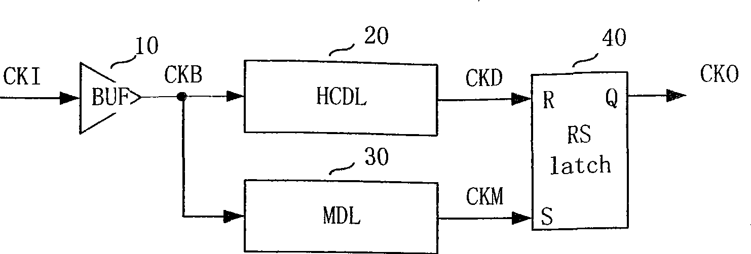
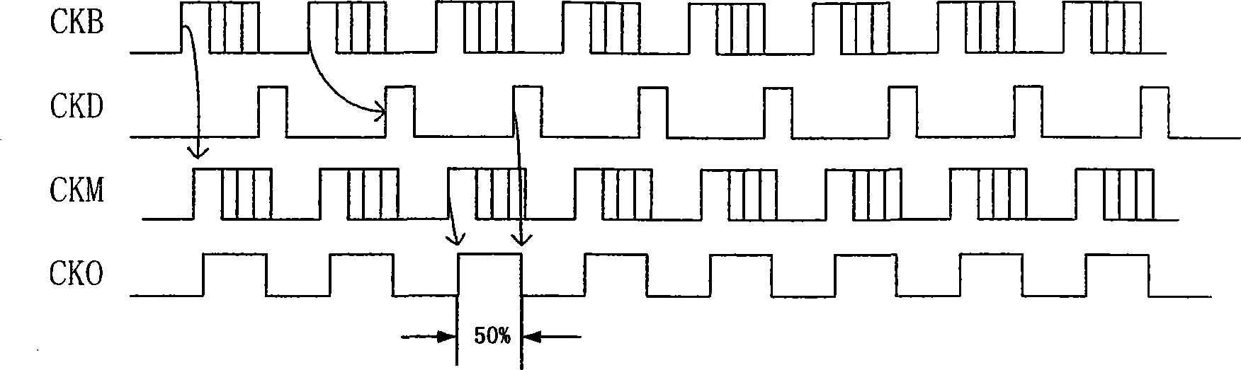
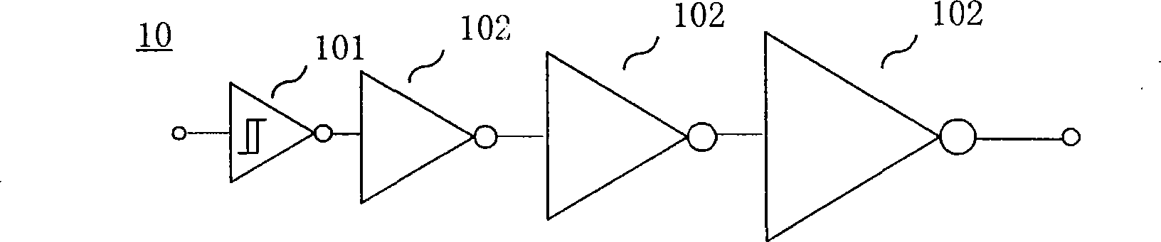
[0035]The input terminal of the input buffer stage 10 in this circuit receives the calibrated original input clock signal CKI; the output signal of the input buffer stage 10 is the buffered input clock signal CKB, which is simultaneously connected to the clock input of the half-period delay line HCDL20 end and the clock input end of the matching delay line 30; the output signal of the half-cycle delay line HCDL 20 is the half-cycle delay clock signal CKD, and the output signal of the matching delay line 30 is the matching delay clock signal CKM respectively connected to the RS flip-flop The reset input terminal R of 40 and the set input terminal S; the signal at the output terminal Q of the RS flip-flop 40 is the calibrated clock signal CKO with a 50% duty cycle after calibration; the function of the input buffer stage 10 is to ensure that the cl...


PUM


Abstract

The invention relates to a digital clock dutyfactor calibration circuit, which is mainly used for calculating the dutyfactor of a system clock in a high-speed data communication system and a DSP system (such as a high-speed data storage device, a pipelining processor, etc.). In the circuit, an input terminal of an input buffer (10) is connected with an original input clock signal (CKI) to be calculated; the output terminal signal of the input buffer (10) that is an input clock signal after being buffered (CKB), the output terminal signal of a half cycle delay line HCDL (20) that is a half cycle delay clock signal (CKD) and the output terminal signal of a matching delay-line (30) that is a matching delay clock signal (CKM) are respectively connected with a reset input terminal R and a set input terminal S of an RS trigger (40); the signal at an output terminal Q of the RS trigger (40) is a calibration clock signal (CKO) with dutyfactor of 50 percent after being calculated; and the input buffer (10) plays the role of ensuring the fan-out ability of the clock signal on a subsequent circuit.

Description

technical field [0001] The invention is mainly used in high-speed data communication systems and digital signal processing systems (such as high-speed data storage, pipeline processors, etc.) to correct the duty cycle of the system clock, and belongs to the technical field of duty cycle calibration circuit design. Background technique [0002] With the advancement of integrated circuit technology, the main frequency of modern digital systems has been continuously increased, and technologies such as double data rate (DDR) and pipelines have been widely used to obtain greater data throughput. Therefore, the digital system also puts forward higher requirements on the signal quality of the working clock. A high-quality clock signal should have the characteristics of fast establishment, low jitter, and low skew, and a 50% duty cycle to ensure that the relevant timing constraints of data signal establishment and retention during transmission are met, and the system can be stable. ...

Claims


Application Information

Patent Timeline
Patent Type & Authority Applications(China)
IPC IPC(8): H03K5/156
Inventor 龙善丽顾俊辉吴建辉余俊张其张萌李红
Owner SOUTHEAST UNIV
Why Eureka
Try Eureka