Method for implementing packet scheduling in switch equipment and switch equipment

A technology of switching equipment and packet scheduling, which is applied in the field of computer communication, can solve problems such as congestion, and achieve the effects of reducing congestion, reducing transmission delay, and high throughput

Inactive Publication Date: 2009-07-08
THE PLA INFORMATION ENG UNIV
View PDF0 Cites 42 Cited by
  • Summary
  • Abstract
  • Description
  • Claims
  • Application Information

AI Technical Summary

Problems solved by technology

[0005] The purpose of the present invention is to provide a method and a switching device for realizing packet scheduling in the switching device, so as to solve the problem that the switching device in the prior art uses a single path for scheduling forwarded messages, which easily leads to congestion

Method used


Image

  • Method for implementing packet scheduling in switch equipment and switch equipment
  • Method for implementing packet scheduling in switch equipment and switch equipment
  • Method for implementing packet scheduling in switch equipment and switch equipment

Examples


Embodiment Construction

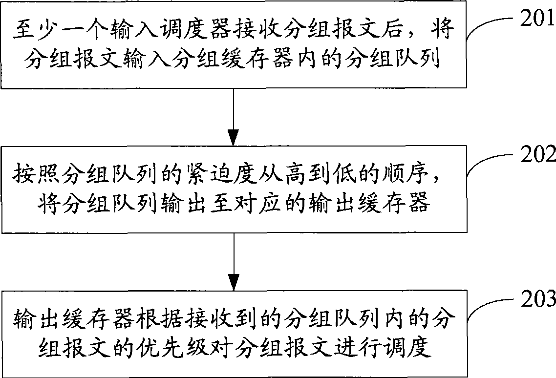
[0054] The core of the present invention is to provide a method for implementing packet scheduling in switching equipment and switching equipment. After at least one input scheduler receives the packet message, it will input the packet message into the packet queue in the packet buffer. According to the urgency of the packet queue from high to high In the lower order, the packet queue is output to the corresponding output buffer, and the output buffer schedules the packet messages according to the priority of the received packet messages in the packet queue.

[0055]In order to enable those skilled in the art to better understand the solution of the present invention, and to make the above-mentioned purpose, features and advantages of the present invention more obvious and comprehensible, the present invention will be further described in detail below in conjunction with the accompanying drawings and specific embodiments.

[0056] The packet scheduling method of the present inv...


PUM


Abstract

The invention discloses a method for realizing packet scheduling in exchange equipment and the exchange equipment. The method comprises the following steps: inputting a packet message into packet queues in a packet buffer after at least one input scheduler receives the package message; outputting the packet queues to corresponding output buffers according to the sequence from high urgent degree to low urgent degree of the packet queues; and scheduling the packet messages according to the priorities of the received packet message in the packet queues by the output buffers. The method can realize packet exchange scheduling; and the packet has a plurality of optional output ports, and the congestion state of dummy output queues at the output terminal is considered fully, thereby reducing the message transmission congestion, improving the transmission efficiency, lowering the transmission delay, and achieving higher throughput of the exchange equipment.

Description

technical field [0001] The invention relates to the technical field of computer communication, in particular to a method for realizing packet scheduling in switching equipment and the switching equipment. Background technique [0002] Switching equipment, as the main node equipment of the Internet, is the key to the connection between networks in the network, including switches and routers, etc. Currently, most high-performance switching equipment adopts a distributed architecture. Since a crossbar is currently the simplest and most commonly used component in high-performance switching equipment, most commercial routers use the crossbar to construct a switching structure. Commonly used crossbar-based switching structures can be divided into queuing mechanisms: OQ (Output Queued, output queuing), IQ (Input Queued, input queuing), CIOQ (Combined Input-Output-Queued, combined input and output queuing) and CIOQ (Combined Input-Crosspoint-Queued, joint input crosspoint queuing)....

Claims


Application Information

Patent Timeline
Patent Type & Authority Applications(China)
IPC IPC(8): H04L12/56H04L12/863
Inventor 汪斌强于婧郑德任周粳迪
Owner THE PLA INFORMATION ENG UNIV
Why Eureka
Try Eureka