
Variable speed scooter

A technology of scooters and movable pedals, applied in the field of scooters, can solve the problems of insufficient input power, inability to go uphill, unfavorable manpower, etc., and achieve the effect of improving driving ability, not being easy to pedal and exert force, and increasing the scope of application

Inactive Publication Date: 2009-07-15
林苏钦
View PDF3 Cites 6 Cited by
  • Summary
  • Abstract
  • Description
  • Claims
  • Application Information

AI Technical Summary

Problems solved by technology

[0002] The two- to three-wheeled scooters currently available in the market mainly rely on one foot to pedal the ground to obtain power and use inertial driving. It needs one foot to frequently pedal the ground, which is not very convenient.
In the published patent literature, the patent No. ZL01237990.5 discloses a flexible double-scooter vehicle. Although the cable can automatically return to its position during the interaction of the two pedals, the vehicle bracket adopts a raised middle part. The mechanism makes the flexible double pedals higher off the ground, the center of gravity of the human body is unstable when pedaling, and there is a feeling of leaning forward and backward when pedaling, which is not conducive to human pedaling force; patent ZL01135643. One-up and one-down interactive bicycles with double pedals, but the chain is completely returned by the spring, one is difficult to install, and the other is that the vibration of the spring can easily lead to detachment
Furthermore, since the habitual distance (i.e. amplitude) of people stepping up and down is about 16cm, the stroke of input power will be limited for this reason, so the scooter of the prior art always inputs power (or kinetic energy) when stepping upright. Insufficient, resulting in the scooter speed is too low and unable to go uphill, and they also have no structural shifting effect

Method used


Image

  • Variable speed scooter
  • Variable speed scooter
  • Variable speed scooter

Examples


Embodiment 1

[0036] Embodiment 1: the return type single-speed scooter of flexible plate.

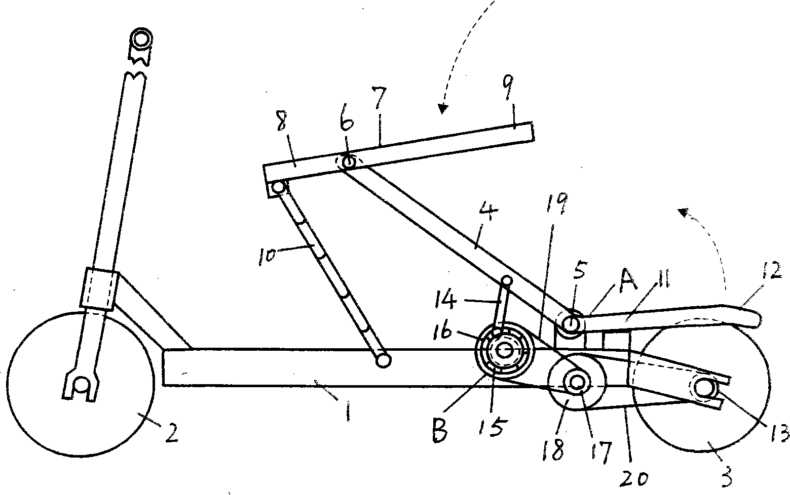
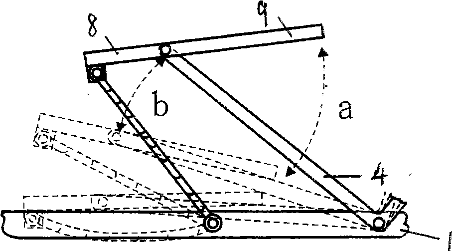
[0037] The speed-changing scooter of this embodiment is a flexible board return type single-speed scooter structure, see figure 1 , it has a car bracket 1, front and rear wheels 2, 3, and a dynamic pressure rod 4 that is movably connected on the top of the vehicle bracket; the power pressure rod 4 is actually movably connected to the vehicle bracket 1 through a shaft 5, and the upper end of the power pressure rod 2 passes through The shaft 6 is movably connected with a movable pedal 7 and the movable pedal is divided into two parts: a limit end 8 and a labor-saving end 9. A movable pedal that can limit the upward movement range of the movable pedal is provided between the front part of the movable pedal limit end and the vehicle bracket. Connecting member 10, the active connecting member adopts a pull cord or a zipper structure, wherein, such as figure 2 As shown, when the labor-saving end point o...

Embodiment 2

[0041] Embodiment 2: the double-speed scooter of flexible board return type.

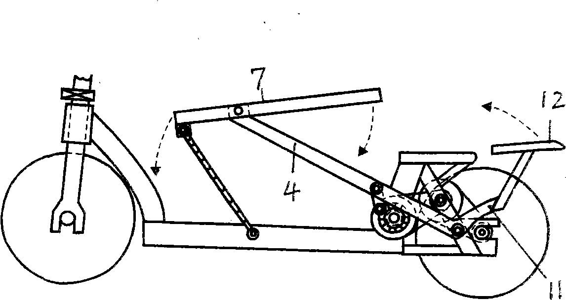
[0042] The variable-speed scooter of this embodiment is a double-speed variable-speed scooter structure with a flexible plate return type, see Figure 18-21 . The difference is that: in Figure 18 Among them, the power pressure rod 4 is two sets of front and rear, which are connected as a whole to directly form a flexible plate structure. In the linkage of one up and one down, they form the return mechanism of the other side. There are two independent sets of ratchets for power output and transmission. 15 system, also known as the different-axis double ratchet structure, one end of the two power pressure rods 14 is respectively movably connected to the outer ring of the different-axis double ratchet 15 through the shaft, and the transmission mechanism includes a coaxial connection with the different-axis double ratchet 15 Two power gears 16, two speed change pinion gears 17 and speed change bull g...

Embodiment 3

[0044] Embodiment 3: Elastic return type single-speed scooter.

[0045] The variable-speed scooter of this embodiment is an elastic return type single-speed scooter structure, see Figure 23 . Its special point is that Figure 23 The return mechanism of the power pressure bar 4 of scooter adopts the extension spring 26 structure that is connected between the power pressure bar and the car support, also can adopt Figure 24 shown in the structure of the torsion spring 27, of course Figure 23 The scooter can also adopt a compression spring structure, Figure 25 bungee cord construction as shown or Figure 27 and Figure 29 Shown shoe hook, shoe cover structure. In fact, the return mechanisms of all the solutions described in Embodiment 1 can be realized by using extension springs, compression springs, torsion springs, elastic cords, shoe hooks or shoe covers.


PUM


Abstract

The invention discloses a gear-shift scooter which comprises a scooter bracket (1), a front wheel (2), a rear wheel (3), a power pressure rod (4) which is movably connected above the scooter bracket, a power pressure rod returning mechanism (A), and a power driving mechanism subassembly (B) which is arranged between the power pressure rod (4) and a driving gear (13) arranged on a wheel shaft. The gear-shift scooter is mainly characterized in that the upper end of the power pressure rod (4) is movably connected with a movable pedal (7) which is divided into a position-limiting end and a labor-saving end, a movable connecting member (10) which can limit the upward motion range of the movable pedal is arranged between the front part of the limiting end of the movable pedal and the scooter bracket, and the power driving mechanism subassembly (B) adopts a connecting rod type driving ratchet wheel rotating structure and a gear-shift driving mechanism. The invention is a scooter with two to four wheels, the pedaling mode conforms to a human body standing and pedaling posture and is easy to smoothly exert force, and meanwhile, the invention has high-class, middle-class and low-class shifting effects and high output power.

Description

Technical field [0001] The invention relates to a reciprocating pedal scooter, in particular to a single-power or double-power scooter with a speed change function. Background technique [0002] Present commercially available two to three-wheel scooter mainly utilizes inertial driving after obtaining power by a pedal of people, and it needs one foot to pedal frequently, which is not very convenient. In the published patent literature, the patent No. ZL01237990.5 discloses a flexible double-scooter vehicle. Although the cable can automatically return to its position during the interaction of the two pedals, the vehicle bracket adopts a raised middle part. The mechanism makes the flexible double pedals higher off the ground, the center of gravity of the human body is unstable when pedaling, and there is a feeling of leaning forward and backward when pedaling, which is not conducive to human pedaling force; patent ZL01135643. It is a bicycle with two-pedal up and down interact...

Claims


Application Information

Patent Timeline
Patent Type & Authority Applications(China)
IPC IPC(8): B62M1/04B62K17/00B62M1/24
Inventor 孙群
Owner 林苏钦
Learn More