High-power LED lamp circuit with fan

A LED lamp, high-power technology, applied in the direction of lamp circuit layout, circuit, circuit layout, etc., can solve the problem that the channel current cannot be cut off, and achieve the effects of low power consumption, long service life and good heat dissipation effect

Inactive Publication Date: 2011-03-16
NANKER GUANGZHOU SEMICON MFG
View PDF0 Cites 2 Cited by
  • Summary
  • Abstract
  • Description
  • Claims
  • Application Information

AI Technical Summary

Problems solved by technology

When a negative voltage is applied between the gate and the source, the channel can be cut off, and the conduction current is zero. The gate voltage at this time is defined as the turn-on voltage, but if the channel concentration is too thick and the depth is too deep, the gate Pole will not be able to intercept the channel current
The depletion-type MOS transistor is not as convenient as the enhancement-type MOS transistor in logic application because the drain-source current is turned on at a constant current when the gate and source voltages are zero, so it has not been isolated by the industry. Make a device to use

Method used


Image

  • High-power LED lamp circuit with fan
  • High-power LED lamp circuit with fan
  • High-power LED lamp circuit with fan

Examples


Embodiment 1

[0027] like Figure 7 As shown, the high-power LED lamp with a fan in this embodiment is a downlight applied in the ceiling, including an LED heat dissipation substrate 20, a metal heat dissipation member 30, a heat dissipation fan 40, a casing 50, a driving circuit board assembly 60, a reflector The cup 70 , the fixing seat 34 , the ring member 81 , the mounting elastic piece 82 , and the clip 83 . The LED heat dissipation substrate 20 is fixedly connected to a plurality of high-power LED chips 10 , that is, the LED load 3 . The LED heat dissipation substrate 20 is mounted on each A cofferdam 21 is fixedly connected to the periphery of the LED chip 10, and the cofferdam 21 is filled with phosphors and optical resins. and optical resin does not overflow, the effect is good, and the production efficiency is high. The LED heat dissipation substrate 20 and the LED chip 10 are provided with an LED protective cover 90 outside. The metal heat sink 30 is a fin type heat sink. The ho...

Embodiment 2

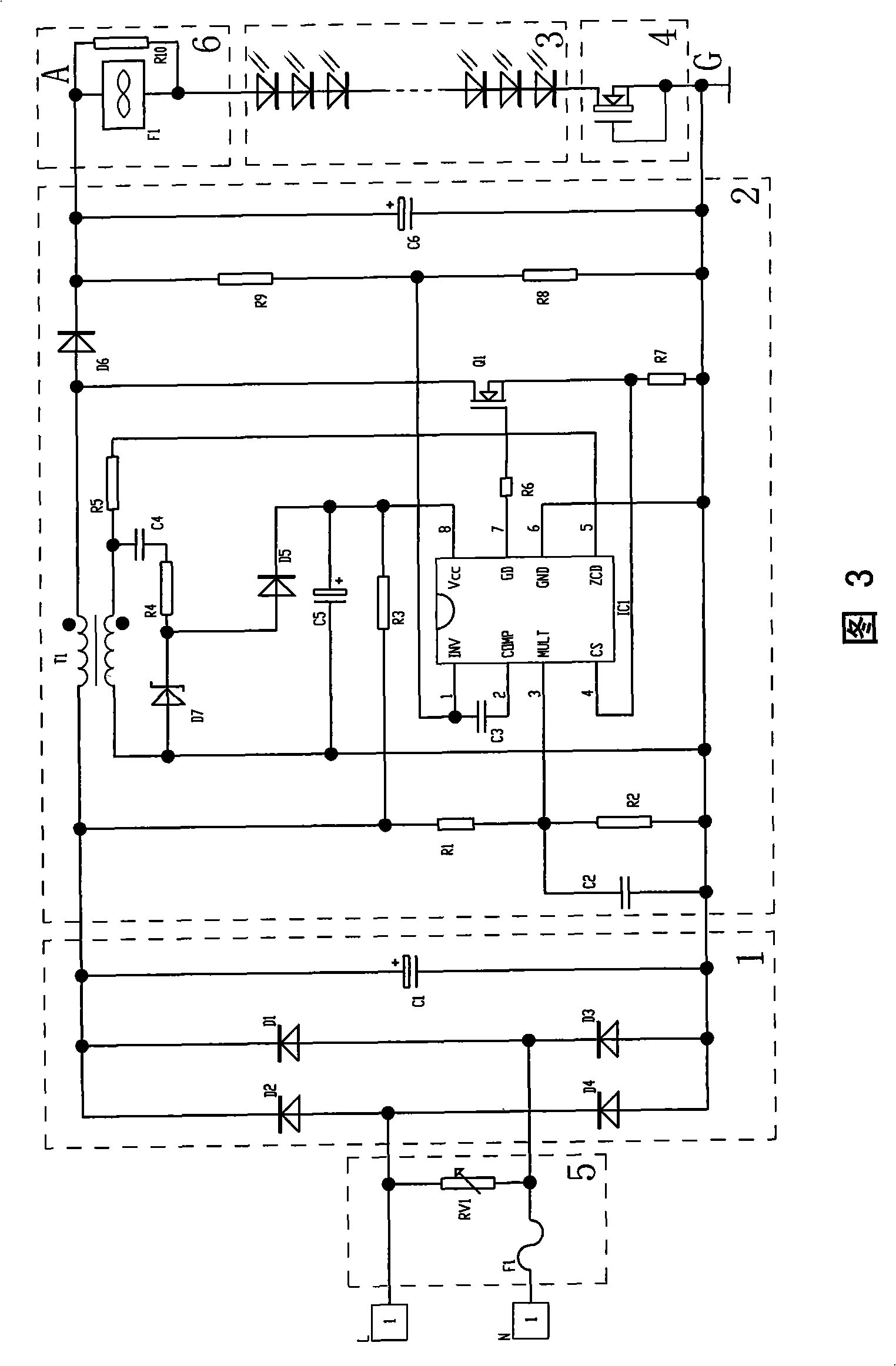
[0040] like Figure 4 As shown, the difference between this embodiment and the first embodiment is that the LED load 3 in this embodiment includes four groups of several LEDs connected in series, and each group of the LEDs is connected in series with one of the constant current source devices 4 , the four groups connected in series are connected in parallel with the fan circuit 6 as a whole, so there are four constant current source devices 4 in this embodiment. In this embodiment, the calculation method of the number of the LEDs connected in series in each group is the same as that in the first embodiment.

[0041] The remaining features of this embodiment are the same as those of the first embodiment.

Embodiment 3

[0043] like Figure 5 As shown, the difference between this embodiment and the first embodiment is that the LED load 3 in this embodiment includes four groups of several LEDs connected in series, and each group of the LEDs is connected in parallel with the fan circuit 6 as a whole. The constant current source device 4 is connected in series, that is, there is only one constant current source device 4 in this embodiment.

[0044] The remaining features of this embodiment are the same as those of the first embodiment.

[0045] Of course, as a simplified form, in the above implementation, the voltage regulator circuit 2 can be omitted, and the DC power can be provided only through the rectification filter circuit 1, which can also achieve the preliminary effect of the present invention.


PUM


Abstract

The invention discloses a large-power circuit for LED lamps and lanterns with fans, which has the advantages of simple structure, high efficiency, low power consumption and energy saving and is capable of prolonging the service life of the lamps and lanterns. The circuit comprises a rectifier filtration circuit (1) and an LED load (3); alternating current is transformed to direct current through rectification and filtration by the rectifier filtration circuit (1) to form an output terminal (A) and a ground terminal (G); the large-power circuit for the LED lamps and lanterns with the fans alsocomprises a constant-current source device (4) and a fan circuit (6); the LED load (3) and the constant-current source device are connected in series and are connected between the output terminal (A)and the ground terminal (G) to form a loop. The circuit can be widely applied to the field of the LED lamps and lanterns.

Description

technical field [0001] The invention relates to a circuit for an LED lamp, in particular to a high-power LED lamp circuit with a fan. Background technique [0002] At present, the application of LED is more and more extensive, and LED lamps for daily indoor lighting are also becoming more and more popular. LEDs are used in daily lighting. In order to meet the illuminance requirements, multiple power LEDs are generally used in one lamp. Therefore, the heat dissipation of LEDs has become an important factor affecting the use status and life of LED lamps, especially for high-power LED lamps. The problem of heat dissipation has become a technical bottleneck affecting its wide application. The existing LED lamps are all passive heat dissipation, that is, the heat dissipation is carried out through the heat sink of the radiator or similar devices. In order to improve the heat dissipation effect, it is necessary to increase the heat dissipation area as much as possible. Complex, ...

Claims


Application Information

Patent Timeline
Patent Type & Authority Patents(China)
IPC IPC(8): F21V23/00F21V29/00H05B37/00H01L23/467F21Y101/02F21Y115/10
CPCY02B20/42H01L2924/0002Y02B20/40H01L2924/00
Inventor 吴俊纬
Owner NANKER GUANGZHOU SEMICON MFG
Why Eureka
Try Eureka