
Reasonable catalytic combustion thermal energy distribution method and equipment of enameling machine

A catalytic combustion, enameling machine technology, applied in the combustion method, combined combustion mitigation, lighting and heating equipment, etc., can solve the problem of not carefully considering the quality of enameled wire, not solve the problem of reasonable heat distribution in the furnace, no heat supply and other problems, to achieve Easy to install and debug, speed up the baking progress, save electricity

Inactive Publication Date: 2009-07-15
DONGGUAN ZELONG WIRE & CABLE
View PDF2 Cites 29 Cited by
  • Summary
  • Abstract
  • Description
  • Claims
  • Application Information

AI Technical Summary

Problems solved by technology

[0006] Another example is the Chinese Utility Model Patent No. 03263874.4, which discloses a technical scheme called "Double-cycle Horizontal Enameller Oven". Injection, but it still does not solve the problem of reasonable heat distribution in the entire furnace, that is to say, there is no heat supply in the middle area of ​​the furnace, and electric heating tubes are still needed for heating
[0007] At the same time, this plan does not carefully consider the quality of the enameled wire. That is to say, the evaporation area of ​​the furnace when the enameled wire solvent is evaporated is the area where the enameled wire is most likely to be polluted by particles. The reference amount of circulating hot air should be considered compared with fresh hot air. The size problem, and the problem of covering the interval
[0008] Also, the plan does not address the issue of how to further reduce emission standards

Method used


Image

  • Reasonable catalytic combustion thermal energy distribution method and equipment of enameling machine

Examples


Embodiment Construction

[0055] Below in conjunction with accompanying drawing and specific embodiment the present invention is described in further detail:

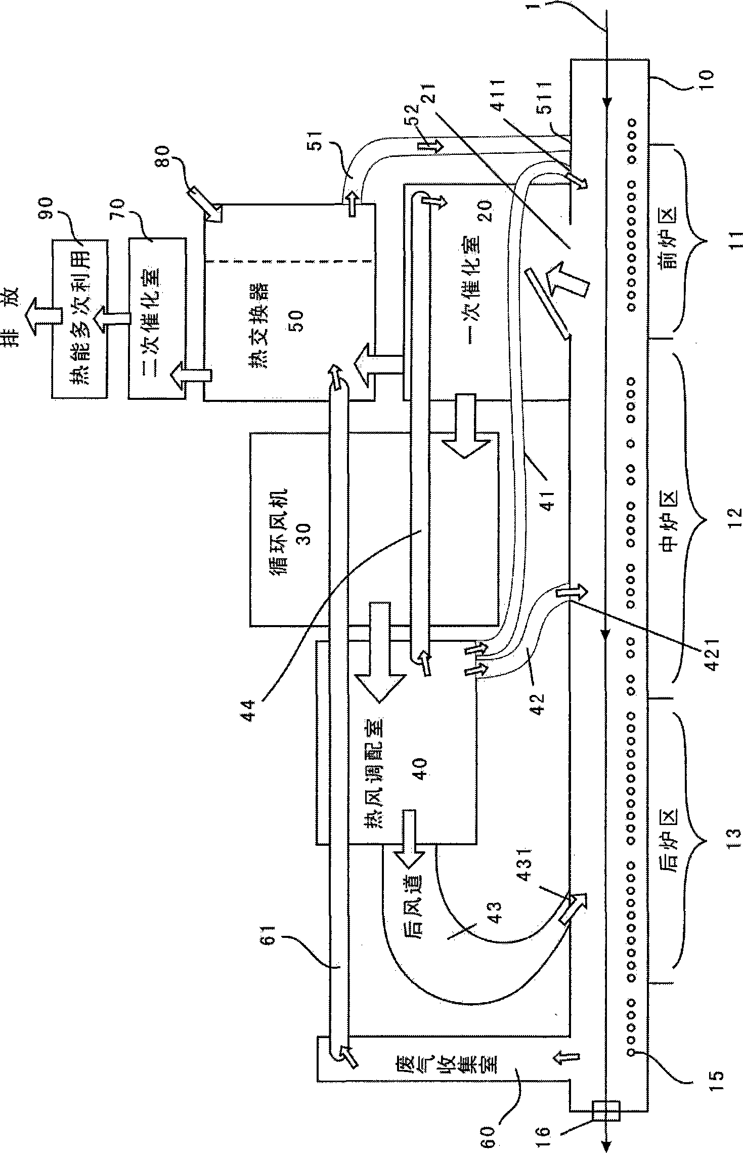
[0056] Such as figure 1 shown in the preferred embodiment,

[0057] Implement a method for rationally distributing catalytic combustion heat energy of an enamelling machine, said method is based on the main furnace body 10, circulating fan 30, heat exchanger 50 and primary catalytic chamber 20 installed with main furnace heating pipe 15; said main furnace heating pipe 15 is used in the preheating process. After the catalytic combustion heat energy reaches a normal cycle, the main furnace heating tube 15 is powered off;

[0058] The method comprises the steps of:

[0059] A. Firstly, a circulation fan 30 is set above the main furnace body 10 near the middle, and a catalytic chamber 20 is set above the main furnace body 10 near the front;

[0060] B. The circulation fan 30 sends the circulating hot air after catalytic combustion into the hot ai...


PUM


Abstract

The present invention provides a method for reasonably distributing catalytic combustion heat by an enamelling machine and a device thereof. A circulating fan is installed on a position which is at the upper part of main furnace body and is next to the middle part. An exhaust organic gas inlet is installed above a front furnace area. A primary catalyzing chamber is provided above the organic gas inlet. A hot air mixing chamber is positioned at the side surface of the primary catalyzing chamber. The circulating fan is communicated with the primary catalyzing chamber and the hot air mixing chamber, and drives the circulating hot air after catalytic combustion into the hot air mixing chamber. The hot gas mixing chamber is communicated with a front furnace area, a middle furnace area and a back furnace area of main furnace body through a front gas passage, a middle gas passage and a back gas passage. The invention quickens the baking process and increases the production efficiency by 20% due to the reasonable distribution of heat. As the exhaust gas is effectively collected and executed with the secondary catalytic combustion, and the circulating hot air is repeatedly executed with the primary catalytic combustion, the discharge standard is reduced to 500mg / m. The invention can save electrical energy by 50% as the catalytic combustion heat is used for baking.

Description

technical field [0001] The invention relates to a method and equipment for baking and drying enameled wire coated paint film, especially an enamelling machine process that uses catalytic combustion heat energy instead of electric energy heating, especially involves using a hot air distribution chamber to rationally distribute catalytic combustion heat energy to various areas of the furnace, and at the same time A method and equipment for lowering emission standards while taking into account the quality of enameled wires. Background technique [0002] In the enameled wire production industry of the prior art, due to fierce competition, the profit is very low, and in terms of cost reduction, except for the energy-saving effect, other potentials have nowhere to be tapped. Some enameled wire manufacturers research and develop energy-saving micro-wire enameled wire machine ovens. The catalytic combustion chamber in the exhaust gas recovery and utilization device is set at one end...

Claims


Application Information

Patent Timeline
Patent Type & Authority Applications(China)
IPC IPC(8): F26B21/00F23G7/07F26B13/00F26B3/02
CPCY02E20/12F26B23/024H01B13/30Y02A50/20
Inventor 叶炽德陈本能盛俊凯陈智方唐国柱
Owner DONGGUAN ZELONG WIRE & CABLE
Learn More